Liquid delivery device based on centrifugal force

A conveying device and centrifugal force technology, applied in the field of centrifugal force-based liquid conveying devices, can solve the problems of inconvenient testing, inaccurate operation, and complexity.

Pending Publication Date: 2019-06-14
DEMODE SUZHOU MACHINERY TECH CO LTD
View PDF0 Cites 0 Cited by
  • Summary
  • Abstract
  • Description
  • Claims
  • Application Information

AI Technical Summary

Problems solved by technology

[0002] When performing sample testing in the life sciences and medical fields, it is necessary to mix the sample with a variety of different reagents, or perform a mixed test with a specific reagent in different proportions to achieve sufficient detection of the sample. Quantitative collection of samples is often required, and the current methods of liquid quantitative collection are either not accurate enough or the operation is relatively complicated, making it difficult to carry out experiments conveniently

Method used


Image

  • Liquid delivery device based on centrifugal force
  • Liquid delivery device based on centrifugal force

Examples


Embodiment 1

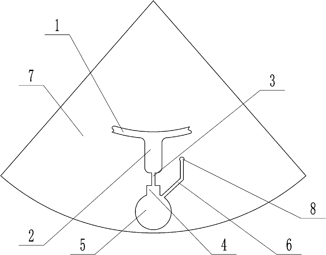
[0012] Example 1: as attached figure 1 As shown, the present invention includes a rotating reagent disk 7, a first chamber 2 arranged on the rotating reagent disk 7, a second chamber 5 communicating with the first chamber 2 through the first flow channel 3, and a variable device arranged on the first flow channel 3. A diameter chamber 4, the inner diameter of the variable diameter chamber 4 is larger than the inner diameter of the first flow channel 3, and the variable diameter chamber 4 cooperates with the first flow channel 3 to form a capillary passive valve. The first chamber 2 , the first flow channel 3 and the second chamber 5 are disposed outward in order relative to the rotation axis. The inner diameter of the lightening chamber 4 suddenly becomes larger relative to the chamber of the first flow channel 3, so that a capillary passive valve is formed in the first flow channel 3. When the rotation speed of the rotating reagent disk 7 is low, due to the action of the capi...

Embodiment 2

[0016] Example 2: as attached figure 2 As shown, on the basis of Embodiment 1, other structures are kept unchanged, and only the position of the variable diameter chamber 4 is changed, so that the variable diameter chamber 4 and the second chamber 5 are connected to form a chamber, and the embodiment can also be realized. 1 effect.


PUM


Abstract

The invention relates to a liquid delivery device based on centrifugal force. The liquid delivery device comprises a rotating reagent disc, a first chamber formed in the rotating reagent disc, a second chamber communicating with the first chamber through a first flow channel and a variable-diameter cavity formed in the first flow channel, the inner diameter of the variable-diameter cavity is greater than the inner diameter of the first flow channel, and thus a capillary tube passive valve is formed. According to the liquid delivery device based on the centrifugal force, the capillary tube passive valve is formed in the first flow channel through the variable-diameter cavity with the inner diameter being increased suddenly in the first flow channel, liquid stays in the first chamber at thelow rotating speed, when the rotating speed is increased, the centrifugal force of the liquid in the first chamber is increased, and the liquid breaks through the restriction of the capillary tube passive valve to flow into the second chamber. The second chamber or the variable-diameter cavity communicates with atmosphere, the situation that a compressible medium is compressed in the second chamber is avoided, and the situation that the positive pressure is generated in the second chamber and prevents the liquid from entering the second chamber is prevented.

Description

technical field [0001] The present invention relates to a centrifugal force-based liquid conveying device. Background technique [0002] When testing samples in the life science and medical fields, it is necessary to mix the samples with a variety of different reagents, or with a specific reagent in different proportions, in order to achieve sufficient testing of the samples. In this process It is often necessary to quantitatively collect samples, and the currently used methods for quantitative liquid collection are either not accurate enough or complicated in operation, making it impossible to conduct experiments conveniently. SUMMARY OF THE INVENTION [0003] The technical problem to be solved by the present invention is to provide a centrifugal force-based liquid conveying device that can realize the transfer of the liquid flowing in the flow channel. [0004] The technical scheme adopted in the present invention is: a centrifugal force-based liquid conveying device, w...

Claims


Application Information

Patent Timeline
Patent Type & Authority Applications(China)
IPC IPC(8): B01L3/00
Inventor 张涛
Owner DEMODE SUZHOU MACHINERY TECH CO LTD
Why Eureka
Try Eureka