Mechanical ripper and multi-station working table

A technology of mechanical claws and manipulators, which is applied in the field of workpiece clamping equipment, can solve problems such as instability, and achieve the effects of saving space and improving production efficiency

Active Publication Date: 2019-06-14
广州益图机电科技有限公司
View PDF15 Cites 6 Cited by
  • Summary
  • Abstract
  • Description
  • Claims
  • Application Information

AI Technical Summary

Problems solved by technology

[0004] The synchronous ring is composed of three parts, which are divided into the outer ring of the synchronous ring, the middle ring of the synchronous ring and the inner ring of the synchronous ring. The three parts are generally circular ring structures. Unsteady phenomenon, so it is necessary to design a jaw for the synchronous ring to grab the synchronous ring, so as to facilitate the assembly of the synchronous ring

Method used


Image

  • Mechanical ripper and multi-station working table
  • Mechanical ripper and multi-station working table
  • Mechanical ripper and multi-station working table

Examples


Embodiment 1

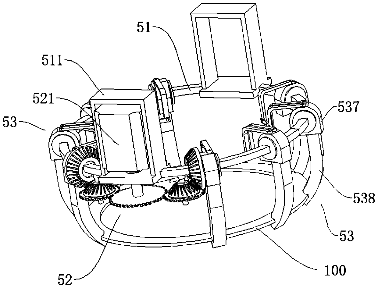
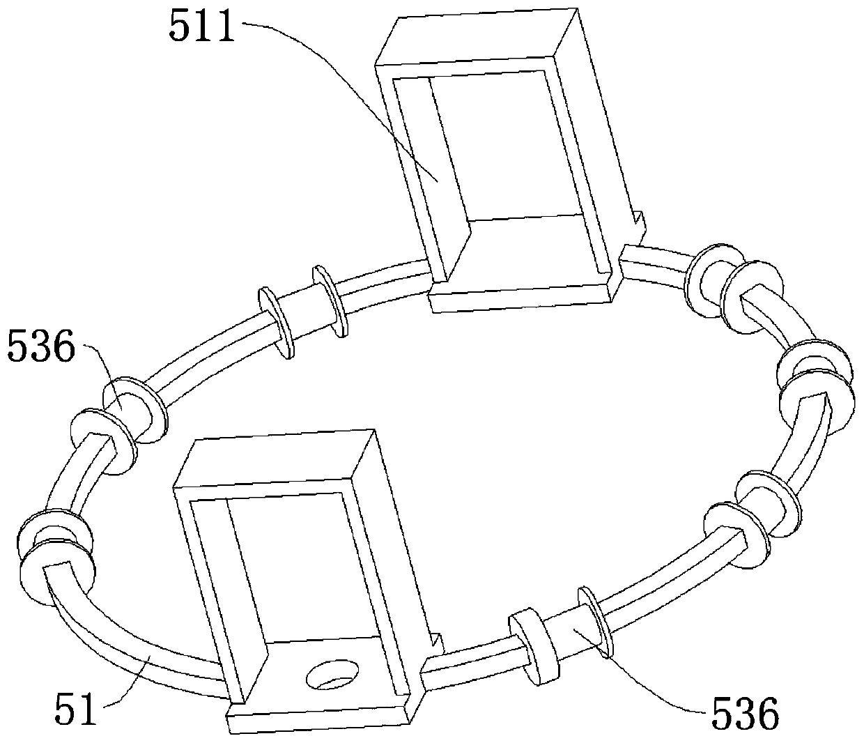
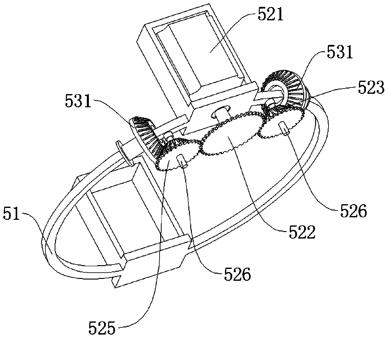
[0031] Such as Figure 1-5 As shown, a mechanical gripper 5 includes an annular support 51, a grasping assembly 53 supported on the annular support 51 to pick up or put down the workpiece 100, and a drive for driving the grabbing assembly 53 to complete the pick up or put down action. Component 52.

[0032] The grasping components 53 have two groups and are arranged symmetrically, and the structures of the two groups of grasping components 53 are identical. Specifically, each grabbing assembly 53 includes four jaws 538 rotatably arranged on the ring bracket 51, the distance between two adjacent jaws 538 is the same, and the free ends of the jaws 538 face toward The center of the ring bracket 51 is bent at a certain angle, and a clamping groove 530 is provided on the side of the jaw 538 near the free end and toward the center of the ring bracket 51, by clamping the workpiece 100 into the clamping groove 530, it is convenient to clamp the workpiece 100 rise.

[0033] Further,...

Embodiment 2

[0042] Such as Figure 6-9 As shown, this embodiment is a multi-station workbench, and the workbench adopts the mechanical claw of the first embodiment.

[0043] The workbench includes a bracket 1 , and the mechanical claw is supported on the bracket 1 through a rotating lifting assembly 2 . The rotary lifting assembly 2 includes a rotary indexing plate 21 supported on the support 1 and a lifting cylinder 22 supported on the output end of the rotary indexing plate 21, the rotation axis of the output end of the rotary indexing plate 21 and the lifting cylinder 22 The cylinder rod is coaxial and vertically arranged, and the free end of the cylinder rod of the lifting cylinder 22 extends upwards, and the free end of the cylinder rod is fixed with a connecting frame 23, and the connecting frame 23 has a plurality of extension arms, and the plurality of extension arms are opposite to each other. Equiangularly arranged on the axis of the cylinder rod, the mechanical claw is fixed o...


PUM


Abstract

The invention discloses a mechanical gripper, comprising an annular rack, grabbing assemblies supported on the annular rack to grab or release a workpiece, and a driving assembly supported on the annular rack to drive the grabbing assembly to finish the actions of grabbing or releasing, wherein two sets of grabbing assemblies are arranged, and each set of grabbing assembly comprises four jaws rotatably arranged on the annular rack, and the distance between every two adjacent jaws is the same and every two adjacent jaws can be in transmission connection with each other, and free ends of the jaws are bent towards the center of the annular rack; the driving assembly is connected with one of the jaws in each set of grabbing assembly. The gripper is able to grip a circular part.

Description

technical field [0001] The invention relates to workpiece clamping equipment, in particular to a mechanical claw and a multi-station workbench. Background technique [0002] The synchronous ring plays a role in synchronizing when the gearbox shifts gears. The synchronous ring has normal pressure type, inertia type, self-energizing type and other forms. The inertial synchronous ring is widely used at present. It is mainly composed of an adapter sleeve, a synchronous lock ring, etc. It is characterized by relying on friction to achieve synchronization. [0003] The shifting of the old-fashioned transmission adopts the "two-leg clutch" method, and the upshift stays in the neutral position for a while (but the clutch needs to be lifted up, the purpose is to synchronize the clutch plate with the flywheel, and the speed must be consistent before the gear can be smoothly shifted , if the gear shifting is slow and the speed drops to idle speed, it cannot be engaged), the downshift...

Claims


Application Information

Patent Timeline
Patent Type & Authority Applications(China)
IPC IPC(8): B25J15/00B65G47/90
Inventor 周武
Owner 广州益图机电科技有限公司
Why Eureka
Try Eureka