Vehicle air filter convenient to clean
An air filter, vehicle technology, applied in the direction of fuel air filter, combustion air/combustion-air treatment, machine/engine, etc., can solve the problem of dirty air, dust on the filter element, and consumption of air filter Resources and other issues, to achieve the effect of comprehensive vacuuming, expanding the area of vacuuming, and increasing the efficiency of vacuuming
- Summary
- Abstract
- Description
- Claims
- Application Information
AI Technical Summary
Problems solved by technology
Method used
Image
Examples
Embodiment 1
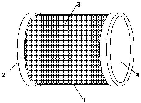
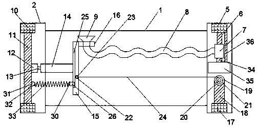
[0027] see Figure 1-3 , according to an embodiment of the present invention, an air filter for a vehicle that is easy to clean includes a housing 1, and an annular mouth frame 2 is symmetrically provided on both sides of the housing 1, and an annular filter screen is provided on the housing 1 3. Both sides of the housing 1 are provided with an air inlet 4, and the annular mouth frame 2 is respectively provided with a negative pressure pump fixing block 5 and a conveyor fixing block 17, and the negative pressure pump fixing block 5 is provided with There is a negative pressure pump support rod 6, the negative pressure pump support rod 6 is provided with a negative pressure pump 7, the negative pressure pump 7 is provided with a suction hose 8, and one end of the suction hose 8 is connected with a suction Dust cover 9, two motor fixing blocks 10 are symmetrically arranged on the annular mouth frame 2, and a motor fixing rod 11 is arranged between the motor fixing blocks 10, and...
Embodiment 2
[0030] see Figure 1-3 , for the conveyor fixing block 17, the upper end of the conveyor fixing block 17 is provided with a conveyor fixing rod 18, and the conveyor fixing rod 18 is provided with a transmission motor 19, and the transmission motor 19 is provided with a transmission motor Shaft 20, the transmission motor shaft 20 is provided with a rope pulley 21, and the side of the circular plate 15 close to the pulley pulley 21 is provided with an annular slot 22, and the ring slot 22 is provided with a rotating The clamping bead 23, a pull rope 24 is arranged between the rotating clamping bead 23 and the pull rope wheel 21.
[0031] By means of the above-mentioned technical scheme of the present invention, the pull cord 24 is rotated by the transmission motor 19 to rotate the stay cord 24, and the stay cord 24 drives the circular plate 15 to move laterally, thereby driving the dust collection cover 9 to move laterally, so that Make the dust collection cover 9 cover the who...
Embodiment 3
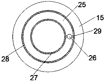
[0033] see Figure 1-3 For the circular plate 15, an annular turning groove 25 is provided on the side of the circular plate 15 close to the motor fixing rod 11, and an inner annular locking groove 27 and an outer annular locking groove 27 are respectively arranged on both sides of the annular turning groove 25. An annular locking groove 28, a first connecting block 26 is arranged in the annular rotating groove 25, and circular locking blocks 29 are arranged symmetrically on both sides of the first connecting block 26, and the circular locking blocks 29 are respectively connected with the inner The annular locking groove 27 and the outer annular locking groove 28 are flexibly connected, the first connecting block 26 is provided with a first spring fixing block 30, and the motor fixing rod 11 is close to the side of the first spring fixing block 30 A second connecting block 31 is provided, and a second spring fixing block 32 is arranged on the side of the second connecting bloc...
PUM
 Abstract
Description
Claims
Application Information
 - R&D
- Intellectual Property
- Life Sciences
- Materials
- Tech Scout
- Unparalleled Data Quality
- Higher Quality Content
- 60% Fewer Hallucinations
Browse by: Latest US Patents, China's latest patents, Technical Efficacy Thesaurus, Application Domain, Technology Topic, Popular Technical Reports.
© 2025 PatSnap. All rights reserved.Legal|Privacy policy|Modern Slavery Act Transparency Statement|Sitemap|About US| Contact US: help@patsnap.com


