Supercharge Your Innovation With Domain-Expert AI Agents!

Two-gear output electromagnetic clutch and its control method

A technology of electromagnetic clutches and output shafts, which is applied in the direction of magnetic drive clutches, clutches, non-mechanical drive clutches, etc., can solve problems such as the inability to use hydraulic clutches, improve energy utilization, reduce electrical control components, and optimize startup characteristics. Effect

Active Publication Date: 2020-10-09
SHANGHAI GKN DRIVE SYST
View PDF8 Cites 0 Cited by
  • Summary
  • Abstract
  • Description
  • Claims
  • Application Information

AI Technical Summary

Problems solved by technology

[0005] In view of the shortcomings of the prior art described above, the purpose of the present invention is to provide a two-speed output electromagnetic clutch and its control method, which is used to solve the problem that new energy vehicles cannot be used in combination with hydraulic clutches in the prior art

Method used


Image

  • Two-gear output electromagnetic clutch and its control method
  • Two-gear output electromagnetic clutch and its control method

Examples


Embodiment 1

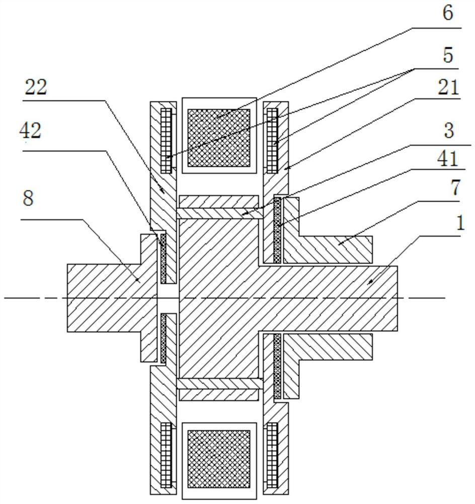
[0043] See figure 1 As shown, this embodiment is output on the same side, that is, the first output shaft 7 and the second output shaft 8 are coaxially sleeved and located on the same side of the input shaft 1 . In order to better realize the power transmission of the input shaft to the above-mentioned first output shaft and the second output shaft, the clutch member 2 in this embodiment is composed of two support plates (that is, the first support plate 21 and the second support plate 22 pass through the middle The rods 23 are connected, that is, the middle rod 23 is fixed between the first support plate 21 and the second support plate 22 .

[0044] In this embodiment, the clutch member 2 formed by two support plates is convenient for installing the above-mentioned electromagnetic clutch assembly. There is a certain interval between the first support plate 21 and the second support plate 22. The coil assembly 6 can be placed in the circumferential groove between the first su...

Embodiment 2

[0050] like figure 2 As shown, the difference between this embodiment and Embodiment 1 is that the first output shaft 7 and the second output shaft 8 are arranged on opposite sides, that is, the power is output on both sides. In this embodiment, the first output shaft 7 and the input shaft 1 are sleeved coaxially, and the second output shaft 8 is arranged opposite to the input shaft 1 and the first output shaft 7 .

[0051] The structure of the clutch 2 in this embodiment is the same as that of the clutch 2 in Embodiment 1, and it consists of two support plates (i.e. the first support plate 21 and the second support plate 22) connected by an intermediate rod. In the example, the first output shaft 7 and the input shaft 1 are coaxially sleeved, the end of the input shaft 1 is located between the two support plates, and the middle rod between the two support plates is passed through the connection at the end of the input shaft. On the disk, that is, the middle rod is used as t...


PUM


Abstract

The invention provides a two-gear output electromagnetic clutch and a control method thereof. The two-gear output electromagnetic clutch comprises an input shaft, an electromagnetic clutch assembly, afirst output shaft and a second output shaft. A clutch piece is arranged at the end portion of the input shaft, the clutch piece and the input shaft axially slide and are in positioning connection inthe circumferential direction, and the clutch piece rotates along with the input shaft. The clutch piece is provided with two opposite friction faces. The electromagnetic clutch assembly comprises apermanent magnet arranged on the clutch piece and an electromagnetic coil assembly generating the magnetic field, and the permanent magnet is arranged in the magnetic field. The end portion of the first output shaft is opposite to the first friction face of the clutch piece, and the end portion of the second output shaft is opposite to the second friction face of the clutch piece. When the electromagnetic coil assembly is powered on, the magnetic field generated by the electromagnetic coil assembly acts on the permanent magnet, and accordingly the clutch piece is driven to axially slide. Through changing of the electrification polarity in the electromagnetic coil assembly, the clutch piece is in friction combination with the first output shaft or the second output shaft through the friction faces. By means of the two-gear output electromagnetic clutch and the control method thereof, two-gear output can be achieved, and the automobile starting character is optimized.

Description

technical field [0001] The invention relates to the technical field of automobile clutches, in particular to a two-speed output electromagnetic clutch and a control method thereof. Background technique [0002] The existing traditional automobile clutches are mainly hydraulic clutches. The main principle is: the oil pump pressurizes the oil, the solenoid valve controls the flow direction of the high-pressure oil circuit, and finally the high-pressure oil acts on the corresponding clutch parts to realize the transmission torque. Output. This type of structure requires a large number of parts, and its manufacturing and assembly are very complicated; there are many electrical control components; and the layout of the oil circuit is relatively difficult. [0003] Existing new energy vehicles mainly adopt the arrangement of the first gear reducer. Under this arrangement, no clutch is needed, and the motor and reducer in the drive system are directly connected together, so the e...

Claims


Application Information

Patent Timeline
Patent Type & Authority Patents(China)
IPC IPC(8): F16D27/01F16D27/115F16D27/12F16D27/14
Inventor 杨亚林余伟苗朱卓选
Owner SHANGHAI GKN DRIVE SYST
Features
  • R&D
  • Intellectual Property
  • Life Sciences
  • Materials
  • Tech Scout
  • Unparalleled Data Quality
  • Higher Quality Content
  • 60% Fewer Hallucinations
Learn More