Heat pipe structure for achieving dropwise condensation

A drop-shaped condensation and heat pipe technology is applied in the field of heat pipes to achieve the effects of easy implementation, enhanced heat transfer efficiency and simple processing method

Pending Publication Date: 2019-06-14
GUIZHOU UNIV
View PDF9 Cites 1 Cited by
  • Summary
  • Abstract
  • Description
  • Claims
  • Application Information

AI Technical Summary

Problems solved by technology

However, the heat pipes currently used are mainly in the film condensation heat transfer mode, and the application of drop condensation in heat pipes does not involve

Method used


Image

  • Heat pipe structure for achieving dropwise condensation
  • Heat pipe structure for achieving dropwise condensation
  • Heat pipe structure for achieving dropwise condensation

Examples


Embodiment 1

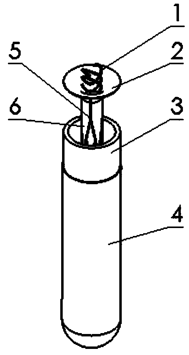
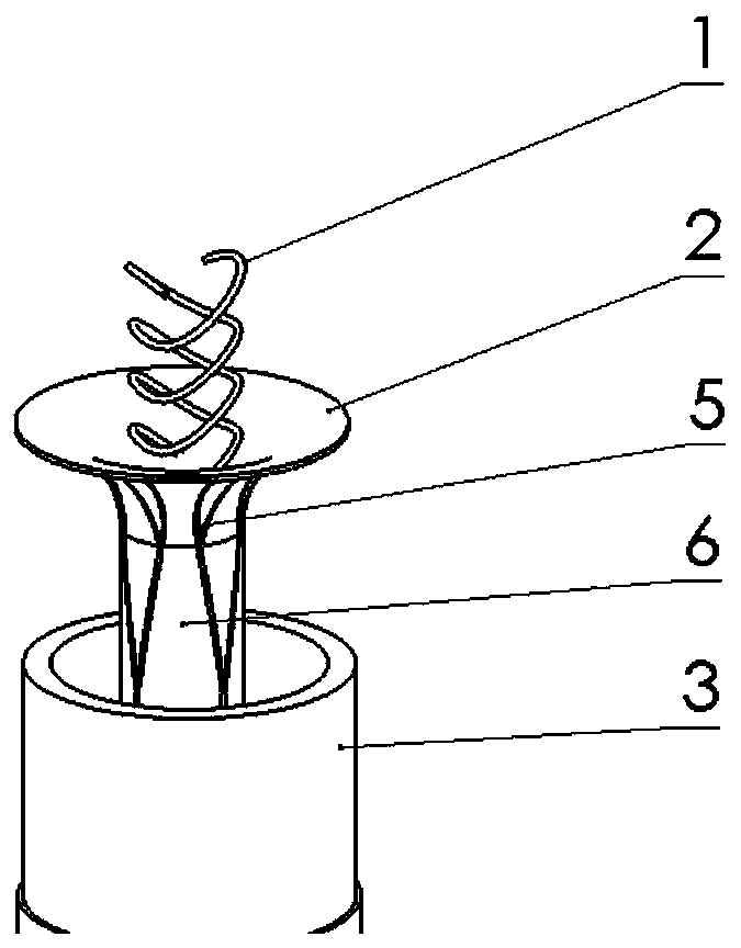
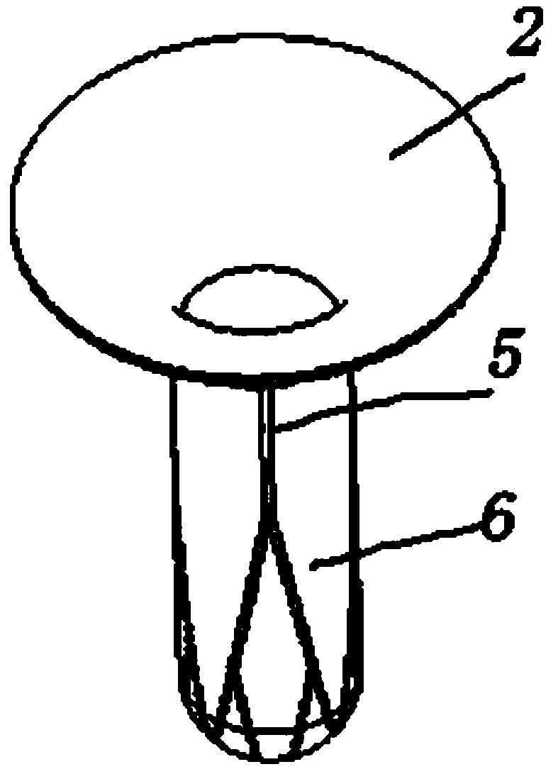
[0028] Embodiment 1: as Figure 1-Figure 7 As shown, a heat pipe structure that realizes droplet condensation, the heat pipe is divided into three sections, that is, the evaporation section, the heat insulation section and the condensation section, including an outer tube 4 with an open upper end and a sealed lower end, a liquid-absorbing core 3, and an open upper end with a lower end. The sealed inner tube 2 and the cooling device 1, the liquid-absorbing core 3 is arranged on the inner wall of the outer tube 4, the inner tube 2 is inserted into the outer tube 4 and the upper end is sealed with the outer tube 4, the inner liquid-absorbing core 3 and the outer surface of the inner tube 2 The gap to keep the steam flowing. The outer surface of the inner tube is the drop-like condensation surface of spider silk. It is made based on the structure and principle of water-absorbing spider silk. The gap is the radial distance between the liquid-absorbing core and the inner tube, which ...


PUM


Abstract

The invention discloses a heat pipe structure for achieving dropwise condensation. The heat pipe structure for achieving dropwise condensation comprises an outer pipe with an open upper end, a wick, an inner pipe and a cooling device, wherein the wick is arranged on the inner wall of the outer pipe, the inner pipe is inserted into the outer pipe, the upper end of the inner pipe is connected with the outer pipe in a sealed mode, a gap is reserved between the wick inside and the outer surface of the inner pipe, and the cooling device is inserted into the inner pipe. According to the heat pipe structure for achieving dropwise condensation, the filmwise condensation enhanced heat exchange mode and the dropwise condensation enhanced heat exchange mode with higher heat dissipation efficiency areboth utilized, so that the heat dissipation efficiency is higher than that of an existing heat pipe with only the filmwise condensation enhanced heat exchange mode.

Description

technical field [0001] The invention relates to a heat pipe structure for realizing droplet condensation, and belongs to the technical field of heat pipes. Background technique [0002] With the proposal of "Made in China 2025", the country will promote the major development of China's manufacturing in the ten major fields, especially in the new generation of information industry, aerospace equipment, energy saving and new energy vehicles and other fields to achieve major technological breakthroughs. In the new generation of information industry, big data storage and big data computing have put forward higher requirements for high-performance integrated circuits and CPUs. In the process of big data storage and computing processing, a lot of heat will be generated, and the damage of more than 55% of the electronic devices on the research surface is caused by excessive temperature. During the operation of aerospace equipment in space, a large amount of heat will also be gener...

Claims


Application Information

Patent Timeline
IPC IPC(8): F28D15/02
Inventor 彭毅朱彬吴宣曹斌张嘉
Owner GUIZHOU UNIV
Why Eureka
Try Eureka