
Encoder detection method

A detection method and encoder technology, applied in the encoder field, can solve problems such as input sine wave waveform distortion, encoder pulse interval deviation, and insufficient performance of interpolation chips

Active Publication Date: 2019-06-14
SHANGHAI MITSUBISHI ELEVATOR CO LTD
View PDF9 Cites 3 Cited by
  • Summary
  • Abstract
  • Description
  • Claims
  • Application Information

AI Technical Summary

Problems solved by technology

[0012] However, in the manufacturing process of the encoder, there is no guarantee that there will be no problems with the relevant devices in each link, and there may also be problems in each process, such as input sine wave offset, input sine wave waveform distortion, and insufficient ADC sampling accuracy , hysteresis effect (only for magnetic encoders), insufficient interpolation chip performance, and inaccurate interpolation algorithms. Under the influence of these factors, there will be a large deviation between the pulse intervals of the square wave output by the encoder

Method used


Image

  • Encoder detection method
  • Encoder detection method
  • Encoder detection method

Examples


Embodiment Construction

[0032] The present invention will be further described in detail below in conjunction with the accompanying drawings and specific embodiments.

[0033] During the manufacturing process of the encoder, some problems inevitably occur, such as input sine wave offset, input sine wave waveform distortion, insufficient ADC sampling accuracy, hysteresis effect (only for magnetic encoder), insufficient interpolation chip performance, Inaccurate interpolation algorithms, etc., will affect the performance of the encoder.

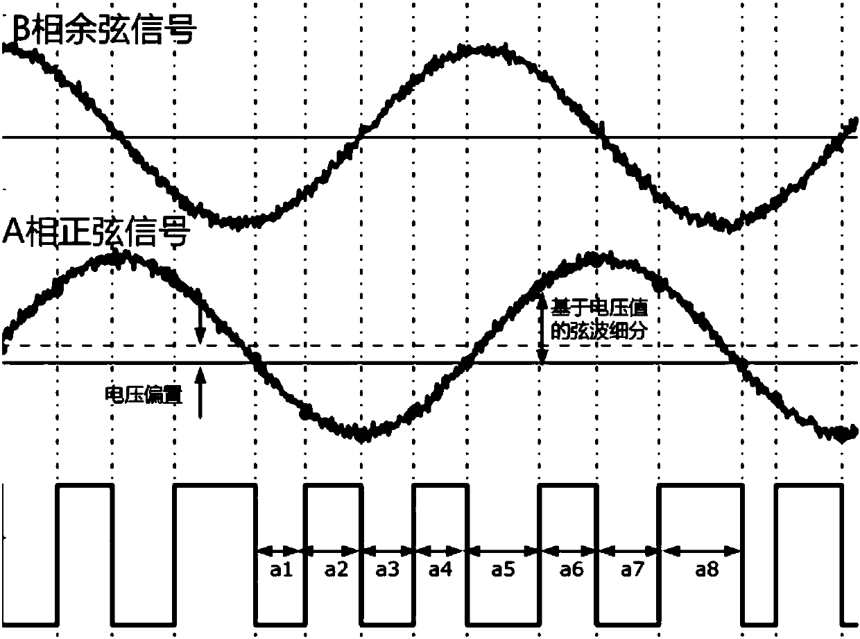
[0034] For example, if image 3 As shown in Fig. 1, the sinusoidal signal of phase A has a voltage offset and noise is superimposed on the waveform, which causes the pulse interval of the square wave output by the interpolator based on the amplitude and phase characteristics to be uneven, that is, a 1 ≠a 2 ≠...≠a n .

[0035] Ideal devices cannot exist in the actual manufacturing process, so the pulse intervals must not be completely equal. However, if there are ...


PUM


Abstract

The invention discloses an encoder detection method. The encoder detection method comprises the following steps: 1, an encoder is mounted on a test bench and dragged by a motor to rotate; 2, a squarewave output by the encoder is detected through a detector; 3, a pulse interval sequence composed of all pulse intervals a1, a2,...a<n> of the square wave in one mechanical rotation cycle is calculated; and 4, all the pulse intervals a1, a2,...a<n> of the pulse interval sequence are subjected to data analysis. The pulse intervals of the output square wave are analyzed through a data analysis method, whether the encoder has defects in the manufacturing process or not is subjected to backward reasoning, and whether the encoder has problems such as bias, waveform distortion and sampling in the manufacturing process or not can be quickly and effectively detected.

Description

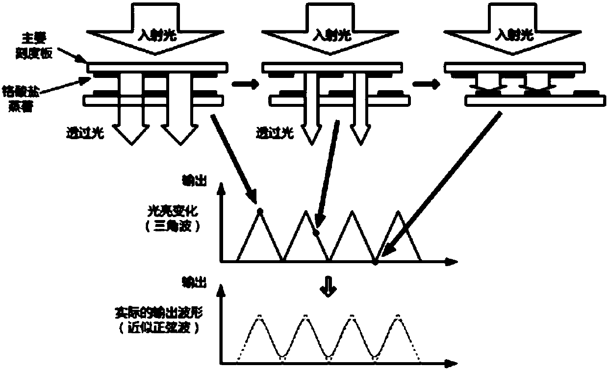
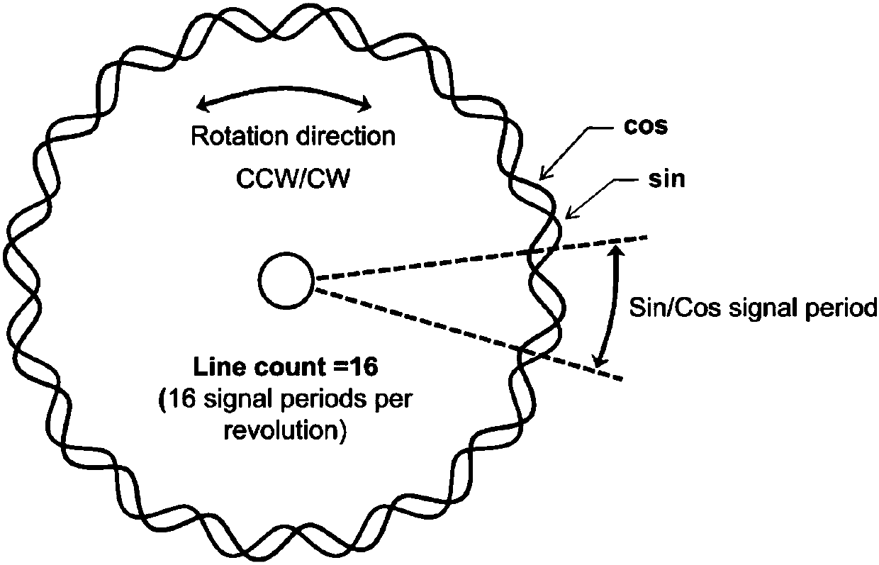
technical field [0001] The invention relates to the field of encoders, in particular to a method for detecting whether an encoder is qualified. Background technique [0002] For optical encoders, such as figure 1 As shown, if the slits of the two gratings in the photoelectric encoder are aligned, the light will pass through completely. If the lines of one grating are exactly opposite the slits of the other, light cannot pass through. The light intensity changes in the form of triangular waves, and the photoelectric unit converts these changes in light intensity into electrical signals close to sinusoidal. From the signal generation principle of the above-mentioned photoelectric encoder, it can be seen that the photoelectric encoder cannot be used for a long time in a working environment with frequent temperature changes, vibration, humidity or serious pollution. [0003] For magnetic encoders, a magnetoresistive sensor is usually used to detect a series of closely arrange...

Claims


Application Information

Patent Timeline
Patent Type & Authority Applications(China)
IPC IPC(8): G01D18/00
Inventor 张筱何晓光季荣斌
Owner SHANGHAI MITSUBISHI ELEVATOR CO LTD
Learn More