Device suitable for acoustic triaxial test, and implementation method thereof

A technology of triaxial test and implementation method, applied in the direction of measuring device, using stable tension/pressure test material strength, instrument, etc., can solve the problems of inability to complete the test, different microstructures, constant contact force, etc., to achieve calculation The results are accurate and reliable, the calculation method is simple, and the confining pressure and flow rate are stable.

Active Publication Date: 2019-06-14
DALIAN UNIV OF TECH
View PDF7 Cites 0 Cited by
  • Summary
  • Abstract
  • Description
  • Claims
  • Application Information

AI Technical Summary

Problems solved by technology

[0003] However, the acoustic wave testing technology has high requirements for the continuity of the material to be tested, and requires a good interface coupling material
Therefore, it is impossible to complete the test by using conventional permeable stones in direct contact with the acoustic probe
At the same time, the contact force between the probe and the coupling material is different, and the microstructure reflected by it is also different. The current three-axis loading equipment cannot realize the constant contact force between the probe and the material to be tested.
At the same time, the flow of the confining pressure of the triaxial equipment also significantly affects the results of the soil material to be tested

Method used


Image

  • Device suitable for acoustic triaxial test, and implementation method thereof
  • Device suitable for acoustic triaxial test, and implementation method thereof
  • Device suitable for acoustic triaxial test, and implementation method thereof

Examples


Embodiment Construction

[0026] A device suitable for acoustic triaxial test and its implementation method of the present invention will be described with reference to the accompanying drawings.

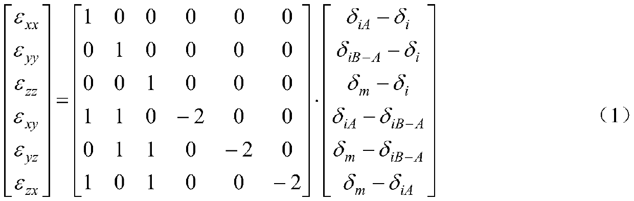
[0027] The device of the present invention suitable for acoustic triaxial test and its implementation method are based on the fact that the rigid shell ensures the zero deformation of the acoustic coupling material, and the stability of the confining pressure is achieved through the progressive compression of the multi-stage chamber body , Calculate the stress state of one point through 6 independent linear strains.

[0028] The device of the present invention suitable for acoustic triaxial test and its implementation method are realized as follows:

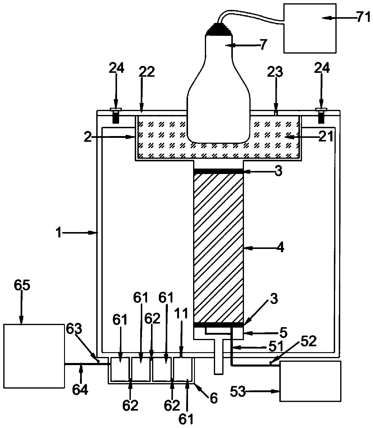
[0029] Propose a device suitable for acoustic triaxial test, such as figure 1 As shown, it is characterized in that the device includes a pressure chamber 1, a couplant storage bin 2, a permeable stone 3, a triaxial soil sample 4, a pressurized base 5, a progressive...


PUM


Abstract

The invention relates to a device suitable for an acoustic triaxial test, and an implementation method thereof, and belongs to the field of geotechnical test calculation. The device comprises a pressure chamber, a coupling agent storage bin, a porous stone, a triaxial soil sample, a pressurized base, a gradual pressurization series bin and an acoustic probe; the top of the pressure chamber is fixedly connected with a pressure chamber cover; the pressure chamber cover and the coupling agent storage bin are integrated; the acoustic probe is put in the coupling agent storage bin, and connected with an ultrasonic acquisition instrument; the gradual pressurization series bin is arranged below the bottom surface of the pressure chamber, and communicated through a pressurization hole; the gradualpressurization series bin is connected with a hydraulic and water-pressure controller; the lower part of the coupling agent storage bin is contacted with the triaxial soil sample; the triaxial soil sample is put on the pressurized base; and the pressurized base is separately connected with a hole pressure sensor and a water quantity collection instrument. The device in the invention is simple instructure and accurate and reliable in calculation result; the problem that contact between the acoustic probe and the triaxial soil sample is non-steady can be overcome; the stability of the confining pressure flow velocity is ensured; and the device can be used for stress state evolution law observation in a triaxial soil sample loading process.

Description

Technical field [0001] The invention belongs to the field of geotechnical test calculations, and relates to a device suitable for acoustic triaxial test and an implementation method thereof, which can be used to evaluate the change law of particle and pore structure during the triaxial test of soil, and to study soil under triaxial loading environment The strain state. Background technique [0002] The structural evolution law and strain state of soil in the process of stress are important indicators reflecting the strength performance. The measurement of the microstructure of the material often uses techniques such as scanning electron microscopy in contact with the external source of the material. The methods used to detect the internal pores and damage of the structure mainly use indirect testing of acoustic wave, electrical and thermal properties. Different from continuous materials, the pores and structure evolution laws of soil can only be revealed in the process of stress...

Claims


Application Information

Patent Timeline
IPC IPC(8): G01N3/02G01N3/06G01N3/12
Inventor 郭晓霞陈之祥邵龙潭于起峰李顺群王鹏鹏赵博雅
Owner DALIAN UNIV OF TECH
Why Eureka
Try Eureka