Device and method for measuring chirp parameter frequency response characteristics of electro-optic intensity modulator

An electro-optical intensity modulation and frequency response technology, applied in the field of optoelectronics, can solve the problems of inability to measure the change of chirp parameters with the modulation frequency, and achieve the effects of simple operation, simple calculation method and accurate results

Active Publication Date: 2013-08-07
UNIV OF ELECTRONICS SCI & TECH OF CHINA
View PDF5 Cites 27 Cited by
  • Summary
  • Abstract
  • Description
  • Claims
  • Application Information

AI Technical Summary

Problems solved by technology

[0007] In view of the above prior art, the object of the present invention is to provide a device and method for measuring the frequency response characteristic of the chirp parameter of the electro-optic intensity modulator, aiming at solving the problem that the chirp parameter of the electro-optic intensity modulator cannot be measured with the modulation frequency in the prior art. changing technical issues

Method used


Image

  • Device and method for measuring chirp parameter frequency response characteristics of electro-optic intensity modulator
  • Device and method for measuring chirp parameter frequency response characteristics of electro-optic intensity modulator
  • Device and method for measuring chirp parameter frequency response characteristics of electro-optic intensity modulator

Examples


Embodiment

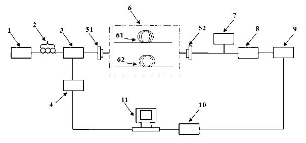
[0043] figure 1 It is a schematic diagram of a device for measuring the chirp frequency response characteristics of an electro-optic intensity modulator provided by the present invention. The light wave with a wavelength of λ output by the tunable laser 1 is input to the electro-optical intensity modulator 3 through the polarization controller 2, and the microwave signal output by the microwave signal source 4 is modulated onto the optical carrier through the electro-optical intensity modulator 3, and the electro-optic intensity modulator 3 The output microwave modulated optical carrier enters the dispersion fiber group 6 through the first optical connector 51, then enters the photodetector 8 through the second optical connector 52, and the electrical signal is output by the photodetector 8, and the power measurement is carried out by the microwave power meter 9. The microwave power is collected by the data acquisition card 10 to the computer 11 for data processing and analysi...


PUM


Abstract

The invention discloses a device and a method for measuring the chirp parameter frequency response characteristics of an electro-optic intensity modulator, and relates to the technical fields of electronics. The device comprises a tunable laser, a polarization controller, a modulator for electro-optic intensity to be measured, a microwave signal source, a first optical connector, a second optical connector, a single mold optical fiber, an optical power meter, a photoelectric detector, a microwave power meter, a data collecting card and a computer, wherein the tunable laser, the polarization controller, the modulator for electro-optic intensity to be measured, the first optical connector, a dispersion optical fiber group, the second optical connector and the photoelectric detector are sequentially connected through optical paths, and the photoelectric detector, the microwave power meter, the data collecting card, the computer and the microwave signal source are sequentially connected through circuits. The device and the method have the advantages that the measurement precision is high, and the operation is convenient. The device and the method have important application prospects in aspects of optical fiber communication systems, electro-optic intensity modulator analysis and optical signal processing.

Description

technical field [0001] The invention belongs to the field of optoelectronic technology, relates to optical fiber communication technology and photoelectric signal processing technology, in particular to a device and method for measuring the frequency response characteristics of chirp parameters of an electro-optical intensity modulator. Background technique [0002] In modern optical fiber communication, the chirp of the optical signal is one of the important factors that limit the high-speed and high-quality transmission of the optical signal in the communication network, so it is also an important parameter to evaluate the quality of the optical signal. The chirp of the optical signal comes from Direct or indirect modulation of a laser signal results in a phase change of the optical signal. [0003] Electro-optic intensity modulator, as a typical electro-optic external modulator, is one of the most basic and critical optoelectronic devices in modern optical communication s...

Claims


Application Information

Patent Timeline
Patent Type & Authority Applications(China)
IPC IPC(8): G01M11/02
Inventor 张尚剑叶胜威邹新海张雅丽刘永
Owner UNIV OF ELECTRONICS SCI & TECH OF CHINA
Why Eureka
Try Eureka