
Video recording shielding device

A technology of shielding device and video recording, applied in image communication, TV, color TV components and other directions, can solve the problems of inconvenience to carry, difficult to detect, interfere with video transmission, etc., to prevent the leakage of personal privacy information, convenient layout, difficult perceived effect

Pending Publication Date: 2019-06-14
创意银航(山东)技术有限公司
View PDF11 Cites 2 Cited by
  • Summary
  • Abstract
  • Description
  • Claims
  • Application Information

AI Technical Summary

Problems solved by technology

[0002] With the continuous advancement and development of science and technology, the video equipment carried by individuals is becoming more and more miniaturized. It is difficult to detect illegal video recordings such as secretly taking pictures of others. This illegal video recording not only seriously affects the parties involved, but even Serious leakage of confidential information
[0003] Some video interference methods currently used are: one is to interfere with the wireless transmission of the camera with wireless transmission function, thereby interfering with the work of the total camera, but for the wireless camera with its own storage hard disk, although the video There is no wireless transmission, but it is stored locally, so the video is still obtained; one is to use a physical method to use the smoke device to protect the target that needs to prevent illegal video recording. This method is easy to be detected, and in the traffic Larger areas are inconvenient to use, and the smoking device is too bulky to be carried around; another is to use the interference to WIFI to interfere with home WIFI cameras, which is still a form of wireless interference in essence.
[0004] The above-mentioned video interference methods or devices have limitations. On the one hand, they are easy to be detected due to their large size and are inconvenient to implement; on the other hand, they can only interfere with video transmission, but cannot interfere with the video itself and its storage.
Therefore, there is no effective video interference device that can directly interfere with the video sensor itself on the market.

Method used


Image

  • Video recording shielding device
  • Video recording shielding device
  • Video recording shielding device

Examples


Embodiment Construction

[0024] Below by embodiment, the present invention is described further in detail.

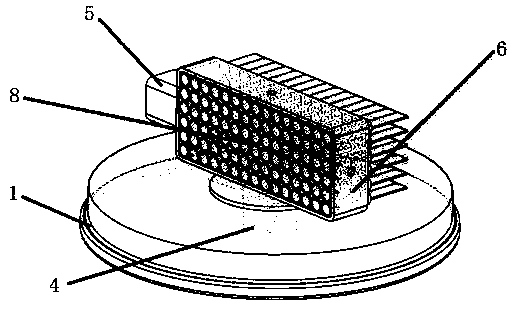
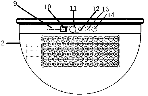
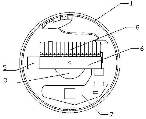
[0025] Such as figure 1 , 2 As shown, a video shielding device includes a base 1 and a scanning mechanism installed on the base 1, a main control board 7 and a direction motor 4 are installed above the base 1, a disc 3 is installed above the direction motor 4, and the main shaft of the direction motor 4 The disc 3 is connected by a bearing, and the disc 3 is slidingly connected to the scanning mechanism through a link cam mechanism; the scanning mechanism includes a pitch motor 5 and a scanning frame 6, and the pitch motor 5 is connected to the scanning frame 6 through a screw slider mechanism, and the scanning frame 6 is installed There are laser arrays 8 .

[0026] The scanning mechanism mainly drives the laser array 8 to reciprocate to form a scanning beam. When the direction motor 4 rotates continuously, the scanning frame 6 reciprocates around the rotation center under the action of the ...


PUM


Abstract

The invention relates to the technical field of image acquisition, and accurately relates to a video recording shielding device, comprising a base and a scanning mechanism installed on the base. The device is characterized in that a main control panel and a direction motor are installed above the base, a disc is installed above the direction motor, and the scanning mechanism driving a laser arrayto move is installed above the disc. The scanning mechanism comprises a pitching motor, a scanning frame and a laser array installed in the scanning frame. The pitching motor is rotationally connectedwith the scanning frame through a bearing. And a cover body is further mounted on the base. The device can directly interfere with imaging itself, cannot obtain normal video data no matter in local storage or wireless transmission, and is small in size and low in power consumption.

Description

technical field [0001] The invention relates to the technical field of image acquisition, and more precisely relates to a video shielding device. Background technique [0002] With the continuous advancement and development of science and technology, the video equipment carried by individuals is becoming more and more miniaturized. It is difficult to detect illegal video recordings such as secretly taking pictures of others. This illegal video recording not only seriously affects the parties involved, but even Serious leakage of confidential information. [0003] Some video interference methods currently used are: one is to interfere with the wireless transmission of the camera with wireless transmission function, thereby interfering with the work of the total camera, but for the wireless camera with its own storage hard disk, although the video There is no wireless transmission, but it is stored locally, so the video is still obtained; one is to use a physical method to us...

Claims


Application Information

Patent Timeline
Patent Type & Authority Applications(China)
IPC IPC(8): H04N17/06H04N17/00H04N5/76
Inventor 牛增强唐文成姜晓建闻天朱道伟崔新国武德光李保庆
Owner 创意银航(山东)技术有限公司
Learn More