Disc ridging and fertilizing machine

A technology of ridge fertilization and disk, which is applied to agricultural machinery and implements, shovels, plows, etc., can solve the problems of low production efficiency, large soil contact area, and large power consumption, so as to improve work efficiency and production efficiency, reduce Small soil contact area, the effect of reducing resistance

Inactive Publication Date: 2019-06-18
宝清县宏达农业机械设备有限公司
View PDF6 Cites 0 Cited by
  • Summary
  • Abstract
  • Description
  • Claims
  • Application Information

AI Technical Summary

Problems solved by technology

[0004] The present invention aims to solve the practical problems of large power consumption, low production efficiency, easy blockage, hanging grass, and large resistance caused by large soil contact area in the prior art, and proposes a disc ridge fertilizer

Method used


Image

  • Disc ridging and fertilizing machine
  • Disc ridging and fertilizing machine
  • Disc ridging and fertilizing machine

Examples


specific Embodiment approach 1

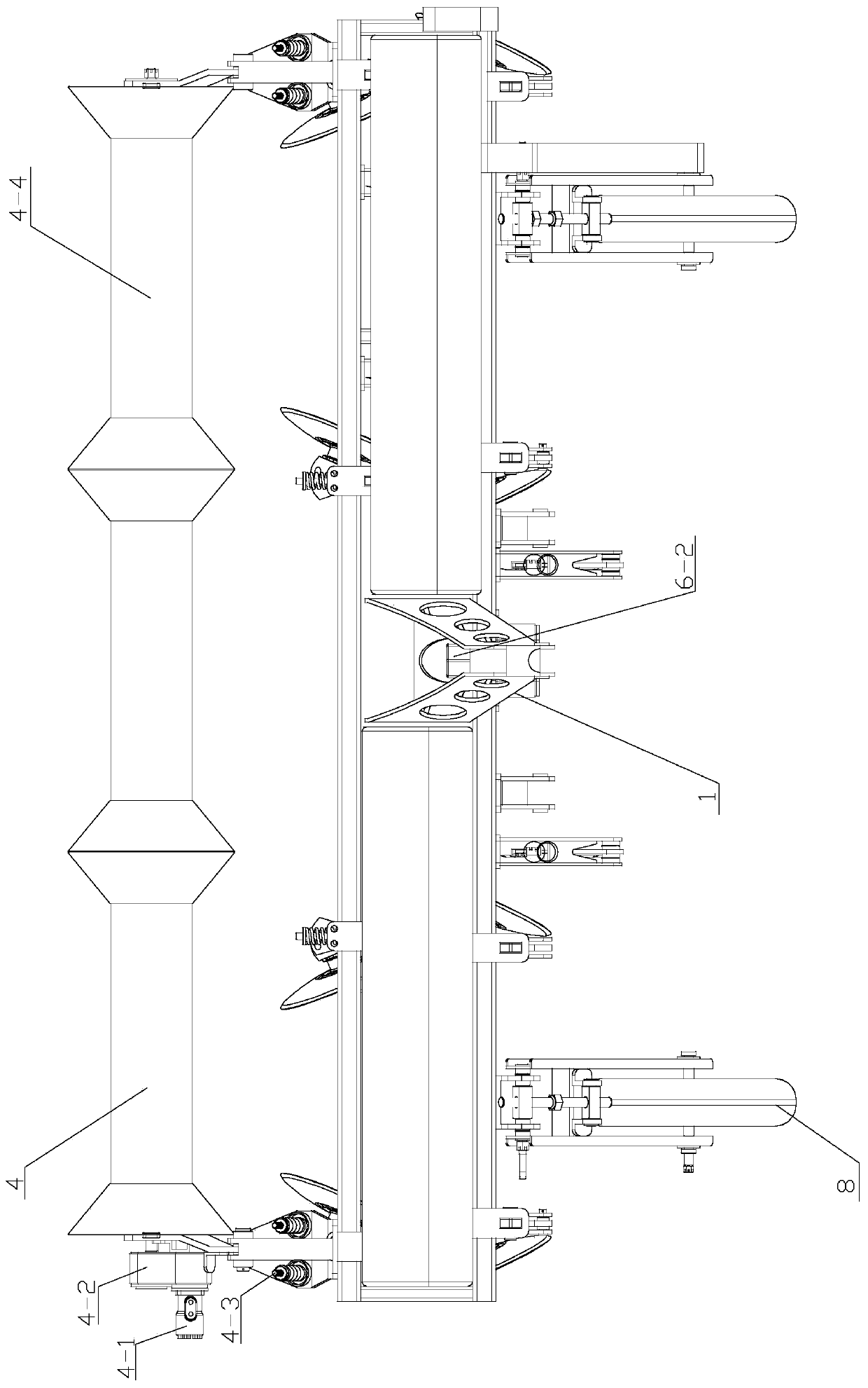
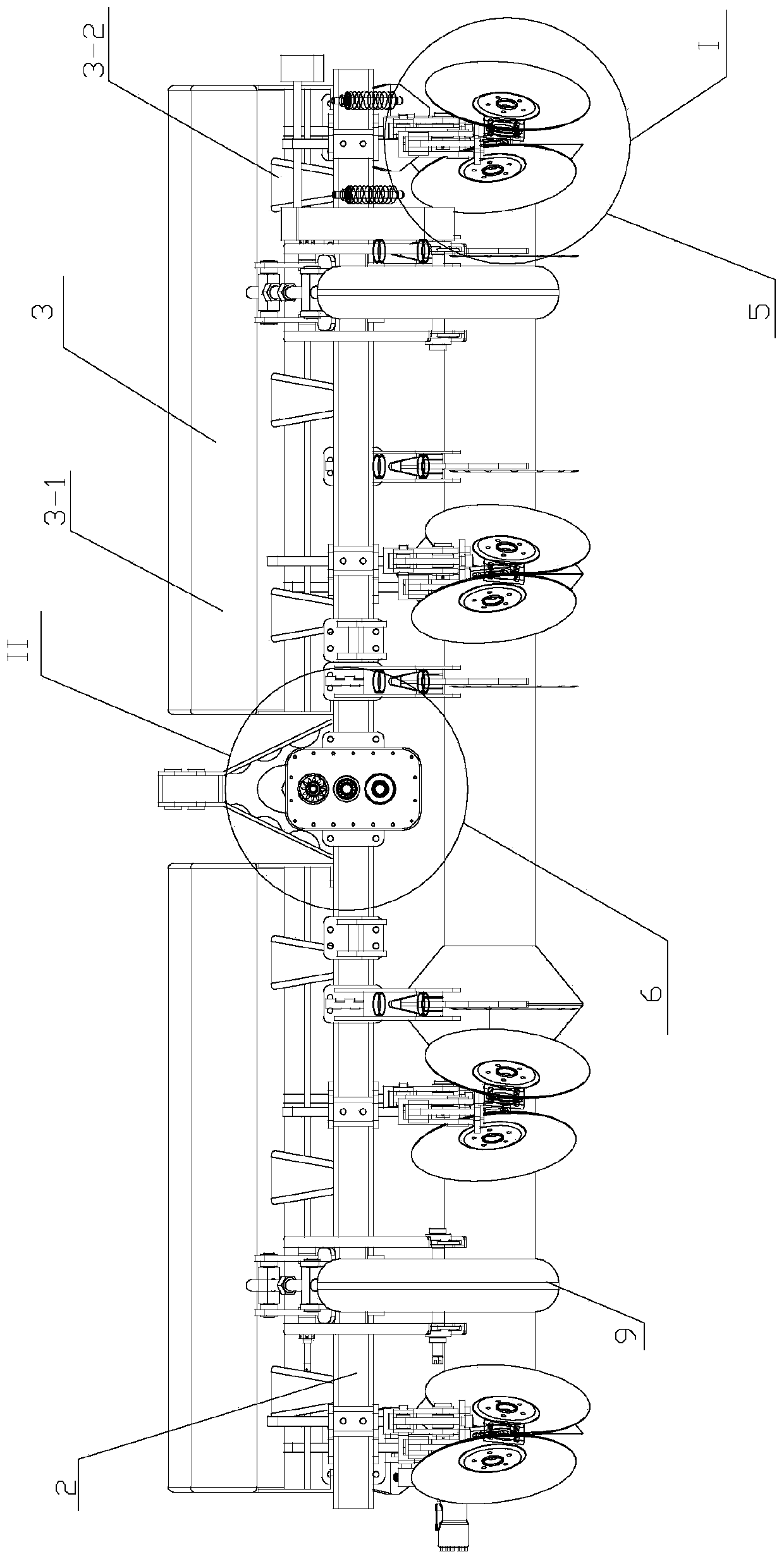
[0019] Specific implementation mode one: combine Figure 1 to Figure 3 Describe a disc ridge fertilization machine of this embodiment, which includes a hanger assembly 1, a main frame 2, a fertilization assembly 3, a shaping assembly 4, a power assembly 6, N soil-distributing disk assemblies 5 and two sub-frames 7. N is an integer greater than or equal to 1;

[0020] Suspension frame assembly 1 is installed on the middle upper part of main frame 2, and two sub-frames 7 are installed on the both sides of main frame 2, and two sub-frames 7 are hinged with main frame 2, and the upper surface of two ends of main frame 2 is set respectively There is a fertilization assembly 3, the center of the main frame 2 is provided with a power assembly 6, the soil distribution assembly 5 is evenly distributed on the front beams of the main frame 2 and the two sub-frames 4, and the shaping assembly 4 is arranged on the main frame in a straight line. Frame 2 and the rear beams of the two sub-fr...

specific Embodiment approach 2

[0021] Specific implementation mode two: combination figure 1 Describe this embodiment. The shaping assembly 4 in this embodiment includes a motor 4-1, a pressing roller drive box 4-2, a No. 1 pressing roller frame 4-3, a No. 2 pressing roller frame 4-5, and a pressing roller 4-4. ;

[0022] The two ends of the main frame 2 are respectively connected with a suppression roller frame 4-3, one end of the suppression roller 4-4 is connected to the inner side of the No. 1 suppression roller frame 4-3, and the other end of the suppression roller 4-4 is connected to the No. 2 suppression roller frame The inner side of 4-5, one side of the suppression roller drive box 4-2 is connected to the outside of the No. 1 suppression roller frame 4-3, and the other side of the suppression roller drive box 4-2 is connected to the motor 4-1.

specific Embodiment approach 3

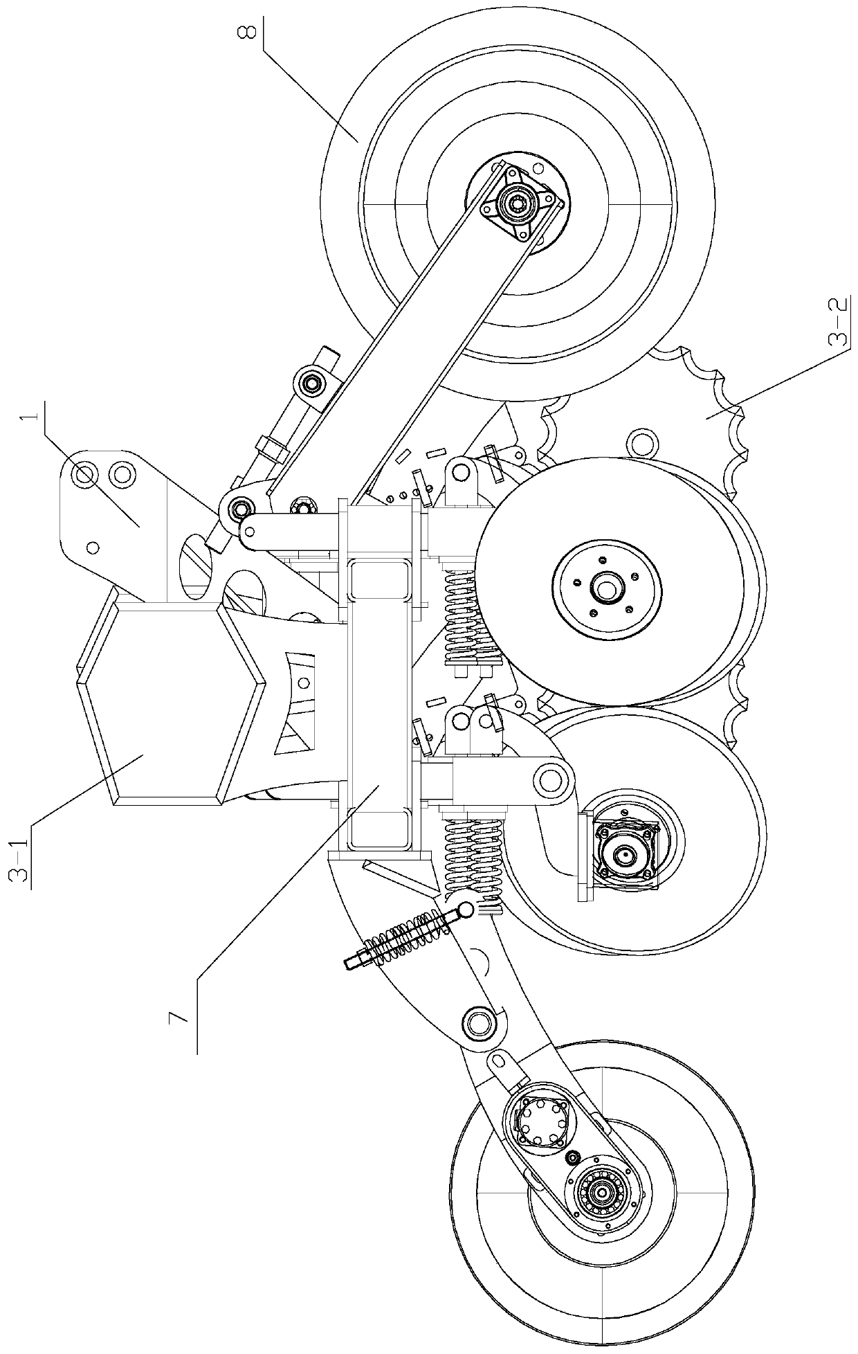
[0023] Specific implementation mode three: combination Figure 4 To illustrate this embodiment, the soil distribution disc assembly 5 described in this embodiment includes a plow column 5-1, a soil distribution disc 5-2 and a soil distribution disc hub 5-3;

[0024] One end of the plow column 5-1 is fixedly connected with the main frame 2 and the sub-frame 7, and the two sides of the other end of the plow column 5-1 are respectively fixedly connected with a sub-soil pan hub 5-3, and the sub-soil pan 5-2 is set On the sub-soil disc wheel hub 5-3, a pair of sub-soil discs 5-2 become V-shaped and are installed on the plow column.


PUM


Abstract

The invention provides a disc ridging and fertilizing machine, and relates to the field of agricultural machinery, and aims at solving the practical problems that the power consumption is large, the production efficiency is low, and easy blockage, grass hanging and large resistance formed by the large soil contact area also exist. A suspension bracket assembly is arranged on the middle upper portion of a main frame, two sub-frames are arranged at the two sides of the main frame, the two sub-frames are hinged with the main frame, the upper surfaces of the two ends of the main frame are providedwith fertilization assemblies respectively, a center part of the main frame is provided with a power assembly, soil distribution discs are uniformly distributed on front beams of the main frame and two sub-frames, and shaping assemblies are arranged on rear beams of the main frame and two sub-frames in a line shape. The disc ridging and fertilizing machine is applied to the filed of agriculturalfertilization.

Description

technical field [0001] The invention relates to the field of agricultural machinery, in particular to a disc ridge fertilizing machine. Background technique [0002] With the development of the economy, the progress of society, the development of agricultural modernization and agronomic technology, and the continuous improvement of machinery manufacturing level, domestic and foreign farming machinery has achieved sufficient development, but there are still many shortcomings in the development of farming machinery in our country. Existing plowshare type ridging machines are generally made of more than 2-5 ditching shovels whose cross-section is a 'herringbone' shape, and the ditching shovels have a large soil contact area, forming a large resistance. The ridging wing is composed of a flat ridge scraper connected to the side of the wing. The ridging wing is located on the upper part of the ditching shovel and is connected with the ditching shovel to form a plow share surface. ...

Claims


Application Information

Patent Timeline
Patent Type & Authority Applications(China)
IPC IPC(8): A01B49/06
Inventor 吴峰葛鹏张洪平
Owner 宝清县宏达农业机械设备有限公司
Why Eureka
Try Eureka