
A Multi-working Condition Pneumatic Robot

A robot and multi-condition technology, applied in the field of robotics and equipment technology

Active Publication Date: 2020-07-17
SHENZHEN LOTUT INNOVATION DESIGN CO LTD
View PDF6 Cites 0 Cited by
  • Summary
  • Abstract
  • Description
  • Claims
  • Application Information

AI Technical Summary

Problems solved by technology

In addition, the pneumatic muscle also has a large power / mass ratio, and the joint can be driven to jump by controlling the on-off valve to inflate, which has been used in the design of bionic robots. Chinese patents CN103241302A and CN108773427A respectively designed a frog with a single pneumatic muscle to drive the joint to jump , robot system, the above-mentioned robot can realize the bouncing motion of switching valve inflation, but it cannot perform precise pneumatic servo trajectory control, pneumatic servo trajectory control and jumping motion switching

Method used


Image

  • A Multi-working Condition Pneumatic Robot
  • A Multi-working Condition Pneumatic Robot
  • A Multi-working Condition Pneumatic Robot

Examples


Embodiment Construction

[0035] The present invention will be further described below in conjunction with the accompanying drawings and specific embodiments.

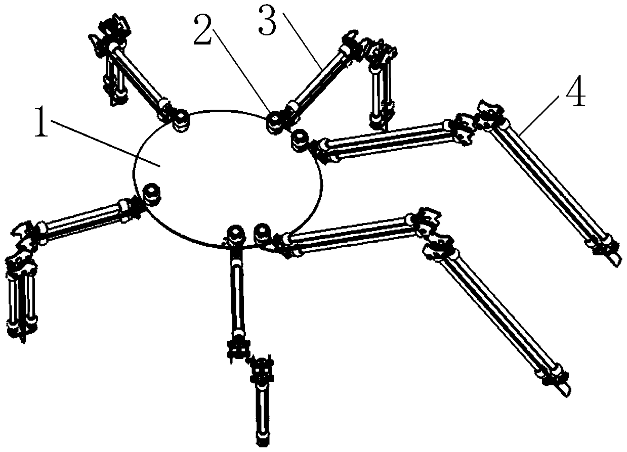
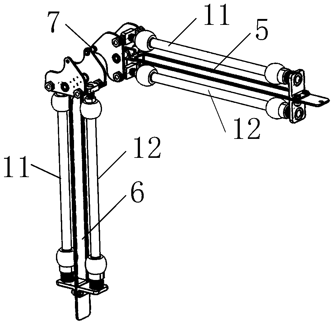
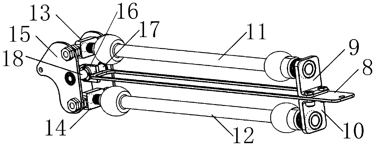
[0036] A multi-working-condition pneumatic robot, comprising: a fixed plate 1, four short legs 3 are arranged on one side of the fixed plate 1, and two long legs 4 are arranged on the other side, and the short legs 3 and the long legs 4 respectively pass through The swing cylinder 2 is fixed on the fixed plate 1, the short leg 3 and the long leg 4 are respectively provided with the first section 5 of the support leg, the second section 6 of the support leg, and the first section 5 of the support leg and the second section 6 of the support leg pass through the support The connecting shaft 7 in the middle of the legs is connected; the first pneumatic muscle fixing plate 9 and the second pneumatic muscle fixing plate 10 are respectively arranged on both sides of the support plate 8 of the first section 5 of the outrigger or the second section 6 of ...


PUM


Abstract

The invention relates to a multi-working-condition pneumatic robot. Two or more pairs of short supporting legs are arranged on one side of a fixing plate. A pair of long supporting legs are arranged on the other side of the fixing plate. The short supporting legs and the long supporting legs are fixed to the fixing plate through swing air cylinders. Each short supporting leg is provided with a supporting leg first section and a supporting leg second section. Each long supporting leg is provided with a supporting leg first section and a supporting leg second section. The supporting leg first sections and the supporting leg second sections are connected with supporting leg middle connecting shafts. A first pneumatic muscle fixing plate and a second pneumatic muscle fixing plate are arrangedon the two sides of one end of a supporting plate of the supporting leg first sections and the supporting leg second sections correspondingly. The other end of the supporting plate is fixed to a connecting shaft connecting part. According to the pneumatic robot, precise pneumatic servo track control is achieved, switching between pneumatic servo track control and hopping motion is achieved, pneumatic muscle and the swing air cylinders are combined for driving, multi-directional motion of joints is achieved at the same time, the pneumatic robot has a large power mass ratio, good flexibility andcompact structure, and hopping obstacle crossing and multi-direction servo track motion control are achieved.

Description

technical field [0001] The invention relates to the technical field of robot equipment, in particular to a precise pneumatic servo trajectory control, which realizes switching between pneumatic servo trajectory control and jumping motion, combined drive of pneumatic muscles and swing cylinders, simultaneously realizes multi-directional movement of joints, and has relatively large power It is a multi-working condition pneumatic robot with mass ratio, better flexibility, compact structure, jumping over obstacles and multi-directional servo track motion control. Background technique [0002] Soft robots have the advantages of light weight, large load-to-weight ratio, variable stiffness, and redundant dexterous operations. Pneumatic muscle robot has the following advantages: (1) In the non-inflated state, the joints can move freely, showing the characteristics similar to human joints; (2) In the inflated state, the displacement and stiffness of the joints can be independently co...

Claims


Application Information

Patent Timeline
Patent Type & Authority Patents(China)
IPC IPC(8): B25J9/10B25J9/14B25J17/00
Inventor 姜飞龙曹坚陈晟张海军朱海滨殷小亮朱荷蕾宋玉来钱承刘睿莹周丽杨立娜
Owner SHENZHEN LOTUT INNOVATION DESIGN CO LTD
Learn More