Transferring mechanical gripper

A mechanical claw and clamping claw technology, applied in the field of transfer machinery and equipment, can solve problems such as easy loosening, and achieve the effects of a wide range of applications, firm and reliable grasping, and a high degree of automation

Inactive Publication Date: 2019-06-18
XIAN ZHIDIAN INFORMATION TECH LTD
View PDF0 Cites 9 Cited by
  • Summary
  • Abstract
  • Description
  • Claims
  • Application Information

AI Technical Summary

Problems solved by technology

[0003] The use of manipulators can not only reduce human physical labor and waste of human resources, but also effectively improve work efficiency; most of the existing manipulators are two-finger clamping manipulators. This

Method used


Image

  • Transferring mechanical gripper
  • Transferring mechanical gripper

Examples


Example Embodiment

[0011] In order to further illustrate the technical means and effects adopted by the present invention to achieve the predetermined purpose, the specific embodiments, structural features and effects of the present invention are described in detail below with reference to the accompanying drawings and examples.

[0012] In the description of the present invention, it should be understood that the terms "center", "longitudinal", "horizontal", "top", "bottom", "front", "rear", "left", "right", The orientation or positional relationship indicated by "vertical", "horizontal", "top", "bottom", "inside", "outside", etc. is based on the orientation or positional relationship shown in the drawings, and is only for the convenience of describing the present invention The description is created and simplified rather than indicating or implying that the device or element referred to must have a particular orientation, be constructed and operate in a particular orientation, and therefore sho...


PUM


Abstract

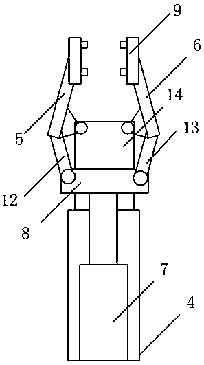
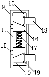
The invention relates to a transferring mechanical gripper. The transferring mechanical gripper comprises a driving part and a clamping part, a clamping mechanism comprises a first clamping gripper and a second clamping gripper, tightly clamping parts are arranged at the top ends of the first clamping gripper and the second clamping gripper, the tightly clamping parts comprise shells, sliding rails are arranged on the tops and the bottoms in the shells, sliding grooves are formed in the inner walls of the right sides of the shells, and two sliding blocks are slidably connected into the slidinggrooves; buffering blocks are fixedly arranged on the sliding blocks, and buffering springs are connected between the buffering blocks in an abutting mode; clamping blocks are arranged between the buffering blocks and the sliding rails, two pulleys are arranged at the left ends of the clamping blocks, and the right ends of the clamping parts are slidably connected with the shells; and the drivingpart comprises a vertically arranged hydraulic telescopic rod, a horizontal pushing rod, a first connecting rod, a second connecting rod and a fixing plate. According to the transferring mechanical gripper, the hydraulic rod drives the first clamping gripper and the second clamping gripper to open or close to realize automatic gripping or releasing, and the automatic degree is high; and meanwhile, the clamping blocks are tightly attached to irregular parts of a clamped work piece under the action of the elastic force of the springs, and gripping is firm and reliable.

Description

technical field [0001] The invention belongs to the technical field of transfer mechanical equipment, and in particular relates to a transfer mechanical claw. Background technique [0002] A manipulator is an automatic operating device that can imitate certain movement functions of the human hand and arm, and is used to grab, carry objects or operate tools according to a fixed program. It can replace human heavy labor to realize mechanization and automation of production, and can operate in harmful environments to protect personal safety, so it is widely used in machinery manufacturing, metallurgy, electronics, light industry and atomic energy departments. At present, the widely used manipulators are four-axis manipulators and five-axis manipulators. Among them, the five motion mechanisms used to drive the mechanical arm in the five-axis manipulator structure are: vertical motion mechanism, swing arm motion mechanism, flip motion mechanism, horizontal motion mechanism and e...

Claims


Application Information

Patent Timeline
IPC IPC(8): B25J15/02B25J15/08B65G47/90
Inventor 路迪
Owner XIAN ZHIDIAN INFORMATION TECH LTD
Why Eureka
Try Eureka