Ultra-narrow wheel track vehicle

A wheelbase and vehicle technology, applied in the field of vehicles, can solve problems such as the inability to achieve a fully enclosed body and easy toppling, and achieve the effects of alleviating environmental pollution and traffic congestion, low energy consumption, and flexible driving performance.

Pending Publication Date: 2019-06-18
杜宇
View PDF0 Cites 1 Cited by
  • Summary
  • Abstract
  • Description
  • Claims
  • Application Information

AI Technical Summary

Problems solved by technology

[0005] The main purpose of the present invention is to provide an ultra-narrow wheelbase vehicle to solve the problems in the prior art that the ultra-narrow wheelbase vehicle is easy to topple when cornering at high speed and cannot realize a fully enclosed body

Method used


Image

  • Ultra-narrow wheel track vehicle
  • Ultra-narrow wheel track vehicle
  • Ultra-narrow wheel track vehicle

Examples


Embodiment 1

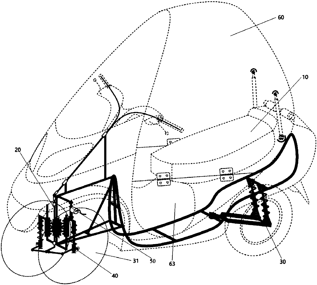
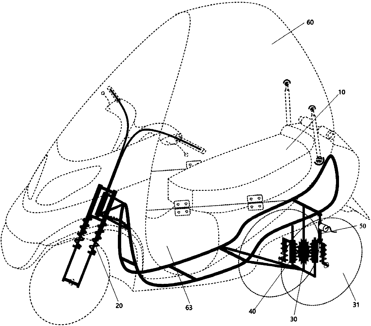
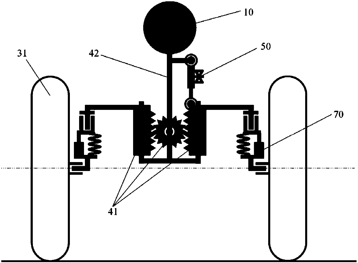
[0071] like figure 1 and figure 2 The shown ultra-narrow wheelbase vehicle includes a vehicle body 10, a steering axle 20, a drive axle 30, at least one tilting device 40 and a canopy 60. The steering axle 20 and the drive axle 30 are respectively arranged at both ends of the vehicle body 10, and the steering The axle 20 or the drive axle 30 has at least two wheels 31, and the wheel distance between any two wheels 31 of the same axle is not more than 60 cm; the tilting device 40 is arranged between the wheels 31 of the same axle, and can achieve ultra-narrow When the wheelbase vehicle tilts, the tilting device 40 is provided with at least one tilting control mechanism 50 , and the tilting control mechanism 50 can control the tilting of the vehicle to ensure that the vehicle does not tip over; around to form an enclosed space.

[0072] Specifically, on the steering axle 20 or the drive axle 30 of the ultra-narrow wheel-base tiltable vehicle, two wheels 31 with a wheel base n...

Embodiment 2

[0100] The difference from the first embodiment is that the tilt control mechanism 50 is a telescopic automatic tilt mechanism.

[0101] Optionally, both ends of the automatic tilting mechanism are respectively connected to the tilting member 41 and the frame 42 , and the automatic tilting mechanism can be extended and retracted to control the tilting angle of the tilting member 41 relative to the frame 42 .

[0102] Specifically, in order to enable the vehicle to autonomously adjust the tilt according to the driving state, an automatic tilt mechanism is provided on the tilt device 40 . The automatic tilt mechanism itself can be extended and retracted, and its two ends are respectively connected to the tilt member 41 and the vehicle frame 42 . On the other hand, by adjusting the expansion and contraction of the automatic tilting mechanism, the tilting angle of the tilting member 41 is controlled to realize the autonomous tilting of the vehicle, and the user no longer needs to a...

Embodiment 3

[0107] The difference from Embodiment 1 is that the tilt control mechanism 50 is a rotary locking mechanism.

[0108] Specifically, as Figure 15 and Figure 16 As shown, the rotary locking mechanism is composed of a brake disc 55, a brake caliper 56, an electric cylinder 522, a housing 54 and a guide positioning structure 57, wherein the brake disc 55 is fixedly connected with the tilting member 41, and the brake caliper 56 and the electric cylinder 522 are installed in the housing 54, the guide positioning structure 57 includes a guide hole, a guide pin and a return spring, the guide pin on the housing 54 can slide in the guide hole on the vehicle frame 42, when the electric cylinder 522 After stretching out, the brake caliper 56 can be promoted to clamp the brake disc 55 from both sides; when the brake caliper 56 did not clamp the brake disc 55, the vehicle could tilt freely, After the disc 55 is clamped, the tilting device 40 will be locked, wherein the brake disc 55 and...


PUM


Abstract

The invention provides an ultra-narrow wheel track vehicle that comprises the following parts: a vehicle body; a steering axle; a drive axle, wherein the steering axle and the drive axle are arrangedat two ends of the vehicle body respectively, the steering axle and / or the drive axle are / is provided with at least two wheels, and the wheel distance between any two wheels of the same axle is not larger than 60 cm; at least one tilting device arranged between the wheels of the same axle, and the tilting devices can achieve tilting of the whole vehicle with the ultra-narrow wheel track; at leastone tilting control mechanism arranged on the tilting device, wherein the tilting control mechanism can ensure that the vehicle with the ultra-narrow wheel track does not tilt by controlling the tilting of the vehicle with the ultra-narrow wheel track; and a cabin cover arranged at the periphery of the vehicle body to form a closed space. The problems that in the prior art that an ultra-narrow-wheel-track vehicle is prone to toppling over when passing through a curve at a high speed and a fully-closed vehicle body cannot be achieved are solved.

Description

technical field [0001] The present invention relates to the technical field of vehicles, in particular to an ultra-narrow wheelbase vehicle. Background technique [0002] Front and rear two-wheeled vehicles are widely used because of their compact structure, low energy consumption, less traffic resource occupation and superior driving performance. At present, two-wheeled vehicles have various forms such as motorcycles, mopeds, and bicycles. However, when the speed is too low, the vehicle will tip over to the side and cannot drive stably, and the rider needs to stretch his legs out to maintain the stability of the vehicle. This defect not only reduces the driving comfort and convenience of the front and rear two-wheeled vehicles, but also causes certain safety hazards. More importantly, it cannot provide a closed driving space for the occupants, which greatly limits the use of the front and rear two-wheeled vehicles. It restricts the further promotion of this green and conve...

Claims


Application Information

Patent Timeline
Patent Type & Authority Applications(China)
IPC IPC(8): B62K5/027B62D17/00
Inventor 杜宇
Owner 杜宇
Why Eureka
Try Eureka