Conveying system of optical fiber disk

A technology of conveying system and optical fiber disk, which is applied in the direction of conveyor, transportation and packaging, etc., can solve the problems of instability, heavy work tasks, unsafety, etc., and achieve the effect of equal power distribution

Pending Publication Date: 2019-06-18
ZTT HUAYU INTELLIGENT TECH CO LTD
View PDF14 Cites 0 Cited by
  • Summary
  • Abstract
  • Description
  • Claims
  • Application Information

AI Technical Summary

Problems solved by technology

The optical fiber reel is a cylinder with large ends and a small middle. There is a round hole on the central axis. The optical fiber is wound in the middle of the optical fiber reel for easy handling. To a certain extent, there will be negative factors such as insecurity or instability

Method used


Image

  • Conveying system of optical fiber disk
  • Conveying system of optical fiber disk
  • Conveying system of optical fiber disk

Examples


Embodiment Construction

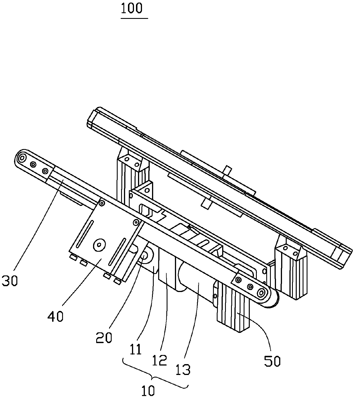
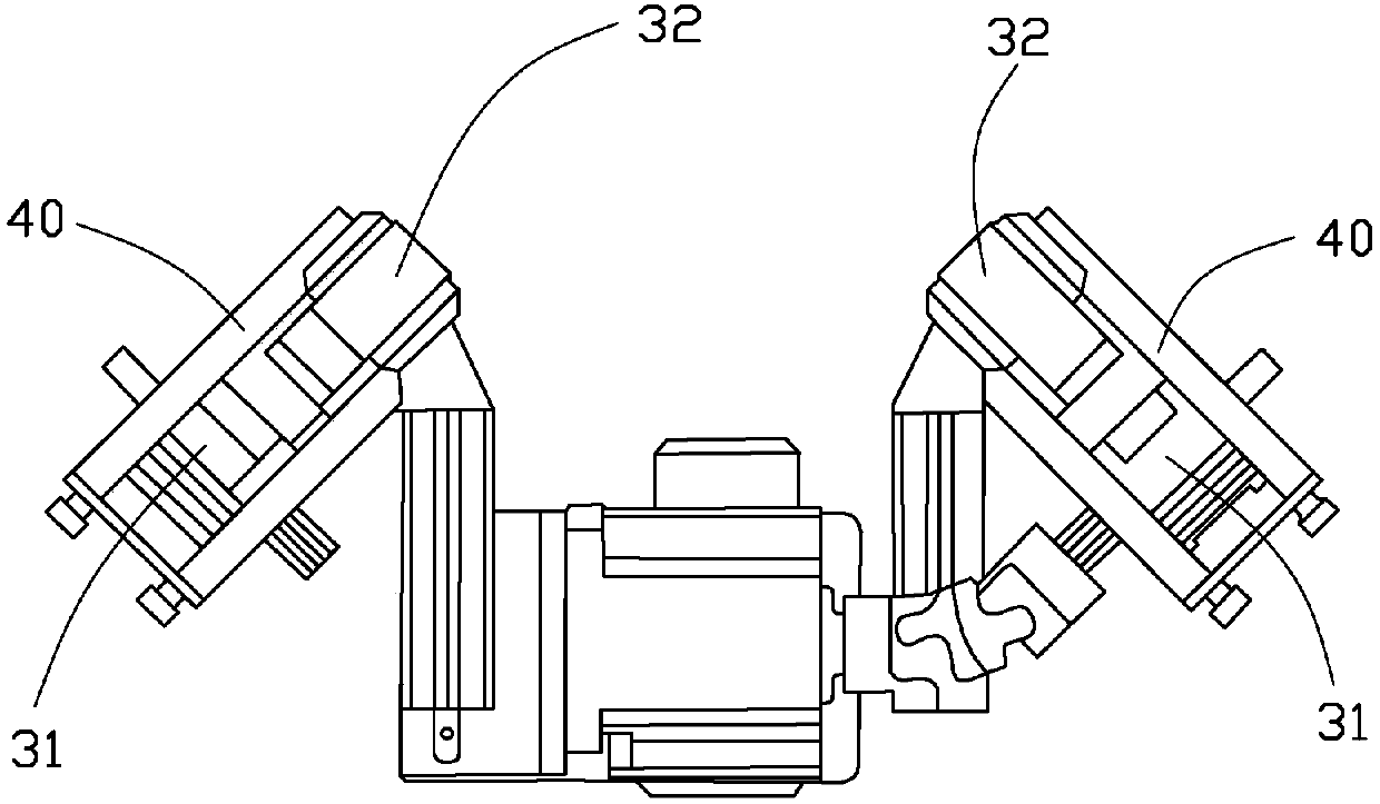
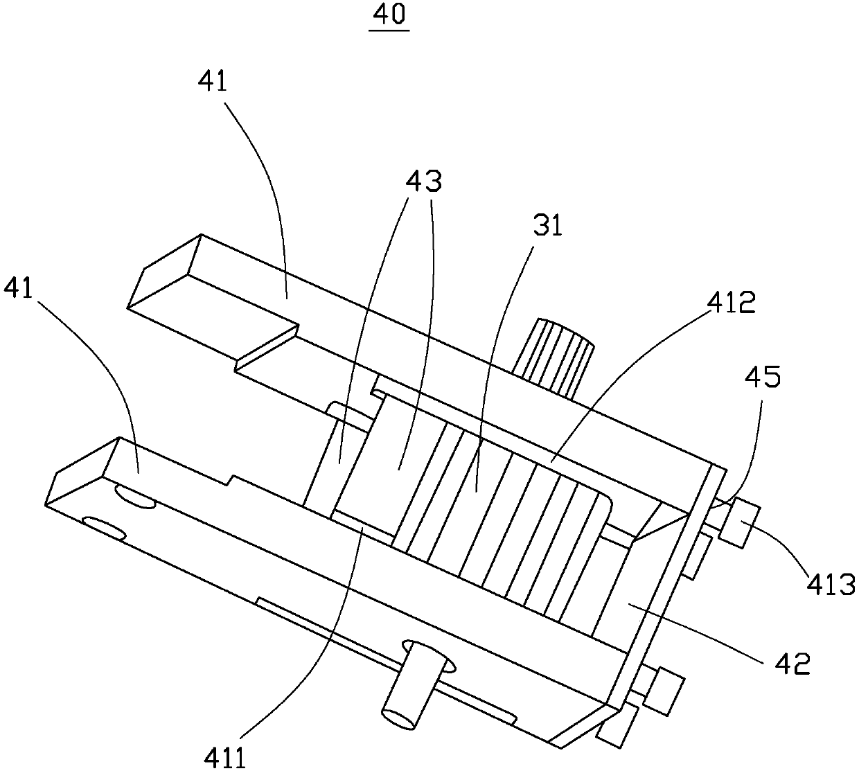
[0019] see figure 1 with figure 2 , an embodiment of the present invention provides a transport system 100 for an optical fiber tray, which mainly includes a power device 10 , a connector 20 , a conveyor belt device 30 , a tensioning mechanism 40 and a bracket 50 . The conveyor belt device 30 includes a synchronous toothed pulley 31 fixedly installed at both ends of the support 50 , and two synchronous toothed belts 32 moving on the synchronous toothed pulley 31 .

[0020] The power unit 10 includes an electric motor 13 , a reducer 12 and a steering gear 11 , the output shaft of the electric motor 13 is connected with the main shaft of the reducer 12 to increase the output torque of the electric motor 13 . One end of the steering gear 11 is connected to the output shaft of the speed reducer 12, and is used to convert the input torque into two synchronously rotating outputs to ensure the synchronous rotation of the two output shafts; the other end of the steering gear 11 pass...


PUM


Abstract

The invention relates to a conveying system of an optical fiber disk. The conveying system of the optical fiber disk comprises a support, a conveyor belt device, a tensioning mechanism, a power deviceand a connection piece. The conveyor belt device comprises synchronous cog belt wheels which are fixedly arranged at the two end portions of the support and two synchronous cog belts which move on the synchronous cog belt wheels. The power device comprises a motor and a steering gear. The connection piece is a cardan joint. The steering gear is connected with the motor and is connected with the synchronous cog belts through the cardan joint. The tensioning mechanism is fixedly arranged at the upper end of the steering gear and located at the middle position of the support. The lower end portion of the tensioning mechanism is connected with the upper end portion of the steering device.

Description

technical field [0001] The present invention relates to a transport system for optical fiber trays. Background technique [0002] With the rapid development of the optical communication industry, the production automation of the optical fiber manufacturing industry is getting higher and higher. In the production process, in order to ensure that the optical fiber does not deform, the optical fiber tray cannot be placed flat and must be placed vertically. The optical fiber reel is a cylinder with large ends and a small middle. There is a round hole on the central axis. The optical fiber is wound in the middle of the optical fiber reel for easy handling. To a certain extent, there will be negative factors such as insecurity or instability. It is becoming more and more urgent to design and develop transportation systems to replace manual operations. Contents of the invention [0003] In view of this, it is necessary to provide a delivery system for optical fiber trays. [0...

Claims


Application Information

Patent Timeline
Patent Type & Authority Applications(China)
IPC IPC(8): B65G15/00B65G23/44B65G23/24
Inventor 苗长朋程晓伟倪红军汪兴兴朱昱黄明宇吕帅帅
Owner ZTT HUAYU INTELLIGENT TECH CO LTD
Why Eureka
Try Eureka