
Anti-seismic pressure-limiting anchor rod head

A bolt and anchor head technology, which is applied in the installation of bolts, mining equipment, earthwork drilling and mining, etc., can solve the problems of difficult quantitative analysis, non-reusable, non-reusable, etc., and achieves wide application range, convenient design and calculation and The effect of the analysis

Pending Publication Date: 2019-06-18
CHINA RAILWAY SIYUAN SURVEY & DESIGN GRP
View PDF0 Cites 2 Cited by
  • Summary
  • Abstract
  • Description
  • Claims
  • Application Information

AI Technical Summary

Problems solved by technology

The common disadvantage of the rod body pressure anchor is that the anchoring force changes nonlinearly with the deformation of the rod body, and the ultimate pulling amount is a limited value, which is expensive, requires high installation requirements, and cannot be reused.
[0006] When the yielding structure of these two types of yielding anchors is deformed or displaced, the anchoring force changes and has a nonlinear relationship, which is difficult to quantitatively analyze; the deformation or displacement of the yielding structure is limited, and the anchor head yielding structure requires Increase the allowable deformation by replacing the relief ring multiple times; the cost of the pressure relief structure of the rod body is high, and the installation requirements are high; it cannot be reused

Method used


Image

  • Anti-seismic pressure-limiting anchor rod head
  • Anti-seismic pressure-limiting anchor rod head
  • Anti-seismic pressure-limiting anchor rod head

Examples


Embodiment Construction

[0029] The following will clearly and completely describe the technical solutions in the embodiments of the present invention with reference to the accompanying drawings in the embodiments of the present invention. Obviously, the described embodiments are only some, not all, embodiments of the present invention. Based on the embodiments of the present invention, all other embodiments obtained by persons of ordinary skill in the art without making creative efforts belong to the protection scope of the present invention.

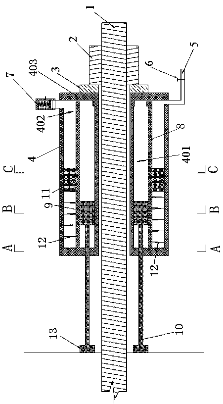
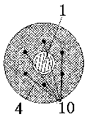
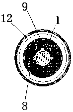
[0030] Such as Figure 1-4 As shown, the embodiment of the present invention provides an anti-seismic pressure-limiting bolt anchor head, including a bolt 1, an annular hydraulic cylinder 4, a damping spring 12 and at least two piston rods 10; the annular hydraulic cylinder 4 is coaxially sleeved on the On the anchor rod 1, and the installation wall 403 of the annular hydraulic cylinder 4 is connected to the anchor rod 1; through the annular partition 8, the i...


PUM


Abstract

The invention belongs to the technical field of anchorage, and specifically relates to an anti-seismic pressure-limiting anchor rod head. An annular hydraulic cylinder coaxially sleeves on an anchor rod, and the anchor rod is connected with a mounting wall; the inner part of the annular hydraulic cylinder is sequentially divided into a first annular cavity and a second annular cavity from inside to outside by an annular baffle; a first annular piston is arranged in the first annular cavity, and a second annular piston is arranged in the second annular cavity; the first annular piston is connected to one end of each piston connecting rod, and the other end of each piston connecting rod extends out of the annular hydraulic cylinder; the second annular piston is connected with one end, away from the mounting wall, of the second annular cavity through a damping spring; the end, deviated from the piston connecting rod, of the first annular cavity is connected with the end, deviated from thedamping spring, of the second annular cavity; and a constant pressure valve is mounted on the side, deviated from the damping spring, of the second annular cavity. According to the anti-seismic pressure-limiting anchor rod head, anti-seismic damping is generated by viscous liquid flowing and deformation of the damping spring, and the constant pressure valve limits the maximum anchoring force to prevent the anchor head from being damaged by impact load exceeding the anchor rod bearing capacity.

Description

technical field [0001] The invention belongs to the technical field of anchor rods and anchor heads, and in particular relates to an anti-seismic pressure-limiting anchor rod and anchor head. Background technique [0002] With the rapid development of highway and railway construction in our country, engineering construction in high-intensity areas puts forward new requirements for the seismic resistance of anchorage engineering. Practice has proved that when earthquakes occur, the damage of anchorage engineering mainly occurs at the anchor head. In the prior art, only springs are added under the anchor head plate to reduce the impact force of the earthquake (referred to as spring anti-seismic anchor). Due to the large anchoring force, the stiffness of the spring is large, the deformation is limited, and the cushioning capacity of the anchor is limited. When When the impact load exceeds the bearing capacity of the anchor, the anchor head will still be damaged, which cannot fu...

Claims


Application Information

Patent Timeline
IPC IPC(8): E21D21/00
Inventor 吴福宝柏威伟朱孟君陈智慧邓云纲王哲张双茁蔡佳俊谢书萌龚标
Owner CHINA RAILWAY SIYUAN SURVEY & DESIGN GRP
Features
  • Generate Ideas
  • Intellectual Property
  • Life Sciences
  • Materials
  • Tech Scout
  • Unparalleled Data Quality
  • Higher Quality Content
  • 60% Fewer Hallucinations
Learn More