
Fastening system

A technology for fastening and tightening elements, applied in the direction of quick-acting fasteners, detachable fasteners with friction clamping, connecting members, etc., can solve the problems of cost, undesired release of clamping protrusions, and work. , to achieve the effect of improving the maximum pull-out force and reliable confinement stability

Active Publication Date: 2019-06-18
ILLINOIS TOOL WORKS INC
View PDF4 Cites 0 Cited by
  • Summary
  • Abstract
  • Description
  • Claims
  • Application Information

AI Technical Summary

Problems solved by technology

Thus, for example during transport of the pre-assembled fastening system, undesired release of the clamping lug from the guide body can result, which in turn leads to further effort and expense in terms of assembly

Method used


Image

  • Fastening system
  • Fastening system
  • Fastening system

Examples


Embodiment Construction

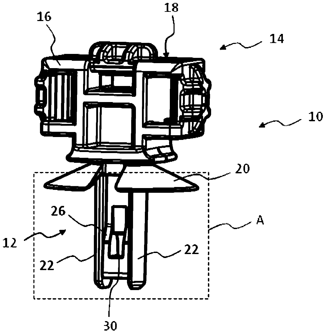
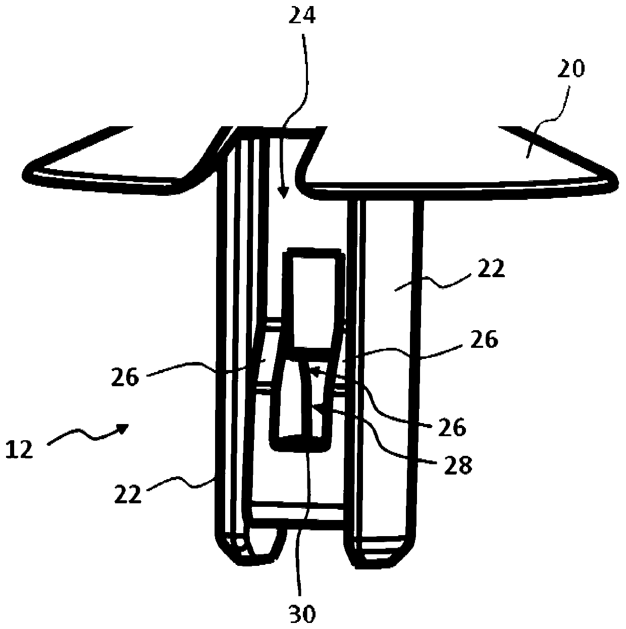
[0038] exist figure 1 and 2 The fastening element 10 shown in has an elongated guide 12 and a head 14 . The head 14 has a holder 16 on which an object, such as a wire harness, can be held. For this purpose, the holding part 16 has, in a manner known per se, a plurality of through-openings 18 through which the cable harness to be held can be drawn. Furthermore, the head 14 has an elastic bearing 20 . Guide part 12 (its longitudinal axis is in figure 1 and 2 Extending in the vertical direction) can be along the insertion direction (in the figure 1 and figure 2 vertically from top to bottom) into the receiving part of the carrier member. In the inserted state into the receptacle, the bearing 20 is supported on the upper side of the carrier part. In the present example, the fastening element 10 is constructed in one piece and is made of plastic. The fastening element 10 can be produced, for example, in a plastic injection molding process.

[0039] The design scheme of g...


PUM


Abstract

The invention relates to a fastening system for fastening in a receptacle of a carrier component. The fastening system includes a fastening element with a guide portion (12) insertable into the receptacle along a direction of insertion, and a clip element which is plugged onto the guide portion and which has retaining edges which interact with an inner surface of the receptacle to hold the fastening element and the clip element in the receptacle, wherein the guide portion and the clip element have interacting latching portions by means of which the clip element is held against the guide portion in a latching manner, and wherein the latching portions are formed in such a way that an axial pulling force to release the fastening element and the clip element from the receptacle produces a radially outwardly acting force on the retaining edges of the clip element, wherein the fastening element and the clip element further have interacting stop portions which counteract release of the clip element from the fastening element.

Description

technical field [0001] The invention relates to a fastening system for fastening in a receptacle of a carrier part, comprising a fastening element having a guide that can be inserted into the receptacle along an insertion direction and comprising a a clipping element on the guide having a retaining edge that interacts with the inner surface of the receptacle to hold the fastening element and the clipping element in the receptacle, wherein the guide and the clipping element have an interacting a latching portion, by which the clipping element is held in a snapping manner relative to the guide portion, and wherein the latching portion is configured such that the axial tension for releasing the fastening element and the clipping element from the receptacle Causes a radially outward force on the retaining edge of the clamping element. Background technique [0002] One such fastening system is known from document DE 10 2014 115 186 B3. In this fastening system, the outer edge o...

Claims


Application Information

Patent Timeline
IPC IPC(8): F16B21/08
CPCF16B13/0841F16B21/086F16B2/20F16B2/243F16B5/0607F16B21/10
Inventor 罗兰·克拉森蒂莫·阿曼
Owner ILLINOIS TOOL WORKS INC
Learn More