Display device, display panel and manufacture method thereof

A technology for a display panel and a manufacturing method, which is applied in the manufacture of semiconductor/solid-state devices, electrical components, and electrical solid-state devices, etc., can solve the problems that light-emitting units are easily eroded by water vapor and oxygen, and achieve the effect of improving service life and increasing distance.

Active Publication Date: 2019-06-18
YUNGU GUAN TECH CO LTD
View PDF8 Cites 10 Cited by
  • Summary
  • Abstract
  • Description
  • Claims
  • Application Information

AI Technical Summary

Problems solved by technology

[0005] In order to solve the problem in the prior art that the light-emitting units around the mounting holes are easily corroded by water vapor and oxygen, the purpose of the present invention is to provide a display panel and its manufacturing method, as well as a display device with the display panel. Compared with the existing The technology can prevent water vapor and oxygen around the installation hole from entering the light-emitting unit, thereby increasing the service life of the light-emitting unit and ensuring the product quality of the display device

Method used


Image

  • Display device, display panel and manufacture method thereof
  • Display device, display panel and manufacture method thereof
  • Display device, display panel and manufacture method thereof

Examples


Embodiment 1

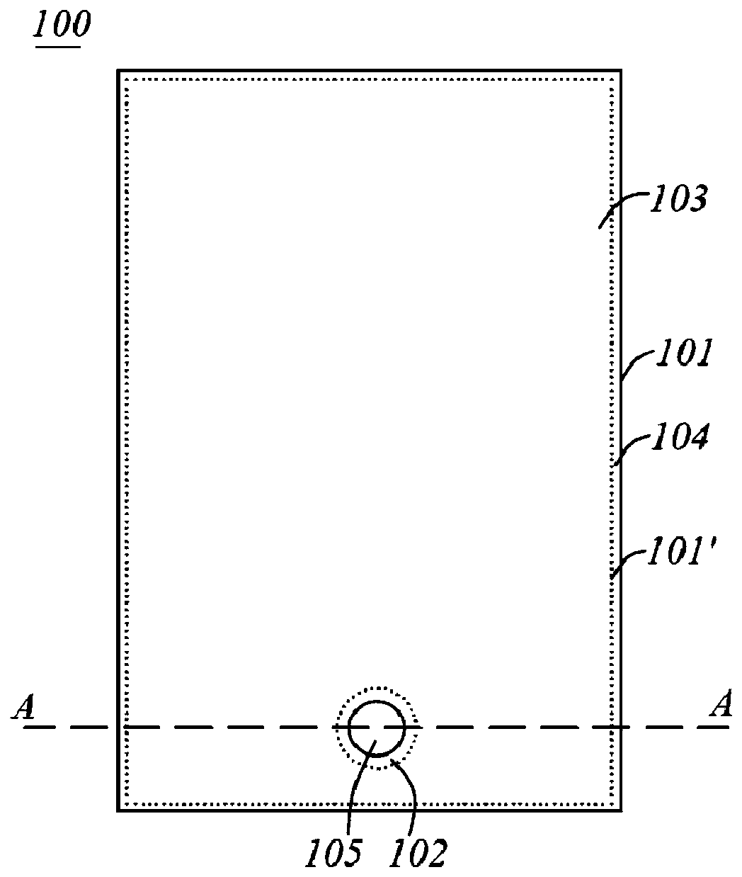
[0060] refer to Figure 1 to Figure 2 An embodiment of the present invention is shown, which provides a display panel 100 . It is preferably set as an organic light emitting display panel, especially an active matrix organic light emitting display panel. The following display panel 100 mainly uses an active matrix organic light emitting display panel as an implementation mode to introduce its specific structure.

[0061] The display panel 100 is roughly in the shape of a thin plate extending along the first surface (that is, it has a relatively large surface area on the first surface and a very small span in the vertical direction of the first surface). figure 1 The projection diagram shown in is along the vertical direction of the first surface. It should be noted that, in the drawings of the present application, the first surface is roughly illustrated as a plane, but in actual implementation, for example, when the display panel 100 is set as a flexible structure, the first...

Embodiment 2

[0139] see Figure 6 , which illustrates another specific implementation of the display panel 100 .

[0140] It is worth noting that this embodiment contains many of the same features as in Embodiment 1, and for the sake of brevity, detailed descriptions of many of the same features are omitted here, and the same symbols used in these drawings and descriptions represent the same components . For example, the structure of the second protection dam in this embodiment is the same as that in Embodiment 1, and both are marked as the second protection dam 16 . For the components in this embodiment that are different from those in Embodiment 1, the combination of the label of the corresponding component in Embodiment 1 and the letter "a" is used to distinguish it from Embodiment 1. For example, in this embodiment and the implementation In Example 1, all have the first protection dam but the specific structure of the first protection dam is different, so it is marked as the first pr...


PUM


Abstract

The invention discloses a display device, a display panel and a manufacture method thereof. The display panel comprises a substrate, a protective dam, and a light-emitting unit, wherein the substratehas a preset hole, a protective area arranged around the preset hole, and a display area isolated from the preset hole by the protective area, the light-emitting unit covers the display area, the protective dam is convex in the thickness direction of the substrate in the protective area, and the protective dam comprises a firm dam, a second dam and a third dam that surround the preset hole in sequence from near to far. The invention further provides a display device comprising the display panel and a method of preparing the display panel. Water and oxygen at the preset hole are prevented fromeroding the light-emitting functional layer.

Description

technical field [0001] The invention relates to a display panel, a manufacturing method thereof, and a display device having the display panel, belonging to the technical field of touch display. Background technique [0002] With the advancement of science and technology, digital display devices such as smartphones and tablet computers are widely used, and display screens are an indispensable human-machine communication interface in these display devices. Such as organic light-emitting display panels (English full name is Orgnic Light-Emitting Diode, hereinafter referred to as OLED), which have the advantages of self-illumination, energy saving, flexibility, etc., and are widely used in terminal products such as smart phones and tablet computers. . [0003] An organic light emitting display panel generally includes an organic light emitting unit and an encapsulation structure. The organic light-emitting unit is used to emit light, and its material is usually sensitive to w...

Claims


Application Information

Patent Timeline
IPC IPC(8): H01L51/52H01L51/56H01L27/32
Inventor 李灏
Owner YUNGU GUAN TECH CO LTD
Why Eureka
Try Eureka