
Full-automatic copper strip machine and operation method thereof

A fully automatic, copper strip technology, applied in the direction of electrical components, circuits, connections, etc., can solve problems such as low precision, complicated use, troublesome use, etc.

Pending Publication Date: 2019-06-18
深圳市瑞峰成机械有限公司
View PDF17 Cites 0 Cited by
  • Summary
  • Abstract
  • Description
  • Claims
  • Application Information

AI Technical Summary

Problems solved by technology

[0003] When the output of the material volume is inconsistent, it is necessary to manually adjust the cam again, which is troublesome to use
In addition, the cam will be worn to an unreasonable degree during long-term use. The longer it is used, the more severe the wear will be. The worn cam needs experienced technicians to adjust the cam accurately.
As a result, the traditional copper belt machine has the characteristics of low precision, low production efficiency and complicated use.

Method used


Image

  • Full-automatic copper strip machine and operation method thereof
  • Full-automatic copper strip machine and operation method thereof
  • Full-automatic copper strip machine and operation method thereof

Examples


Embodiment 1

[0073] Embodiment 1: the concrete structure of full-automatic copper strip machine of the present invention is as follows:

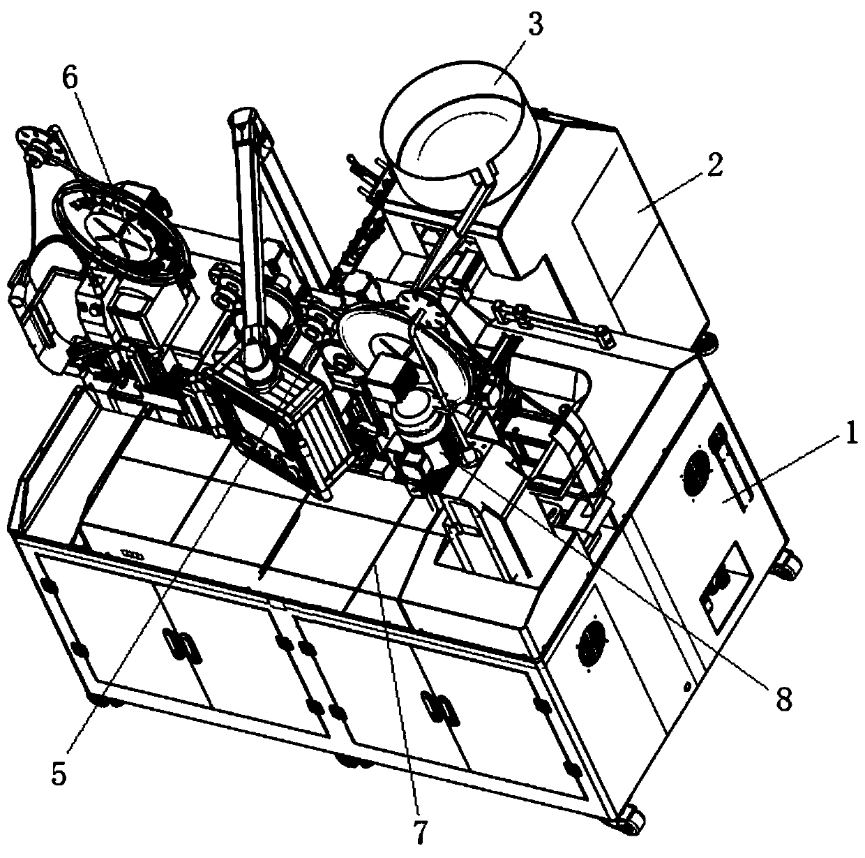
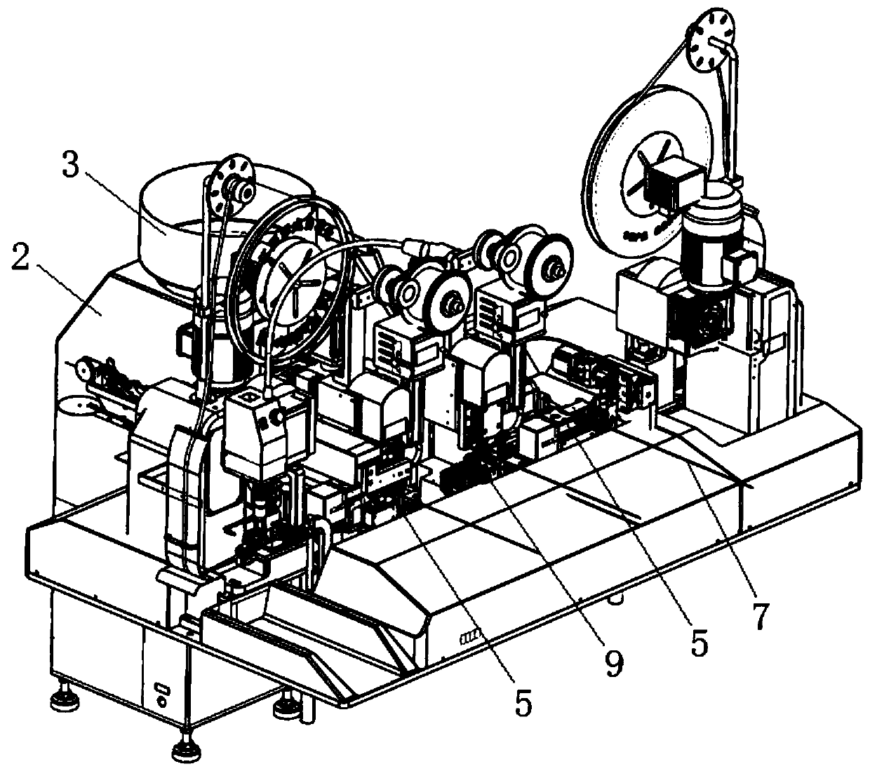
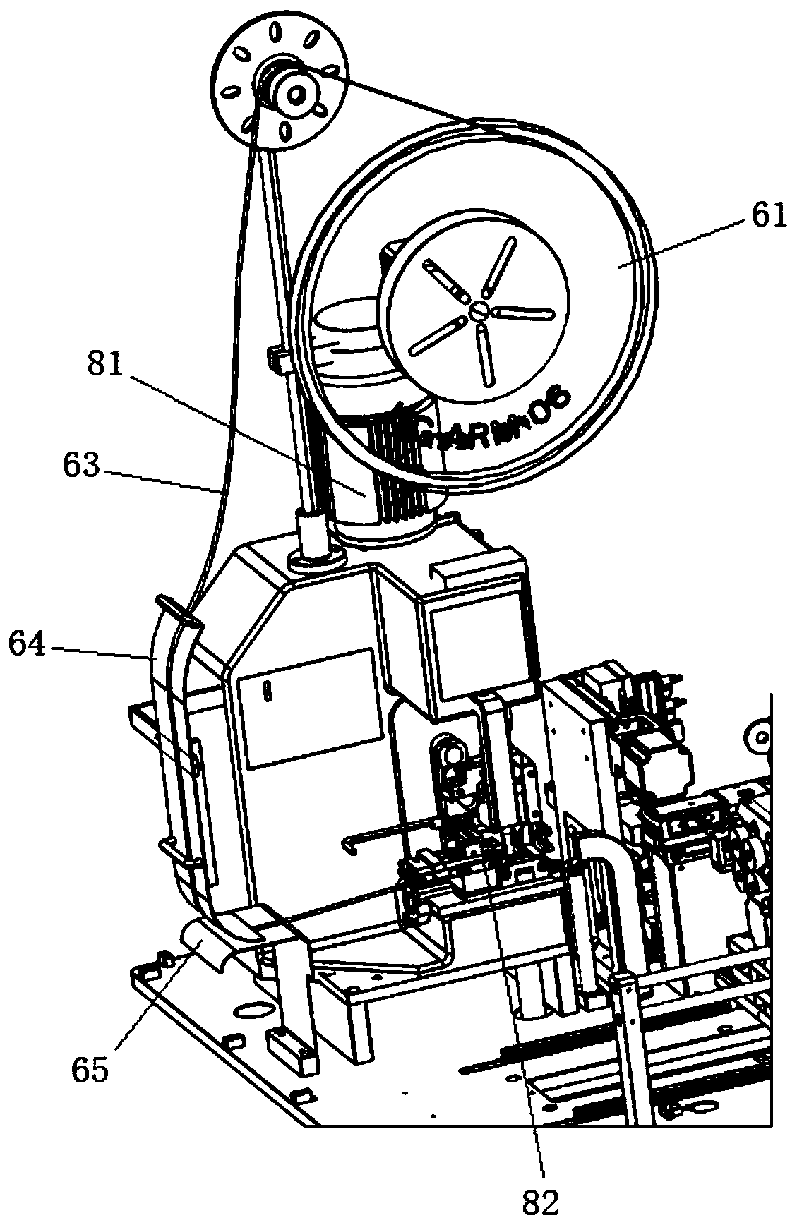
[0074] Please refer to the attached Figure 1-24 , a kind of fully automatic copper strip machine of the present invention, this fully automatic copper strip machine comprises frame 1, also comprises:

[0075] A vibrating device 2 arranged on one side of the frame 1, the vibrating device 2 is provided with a vibrating mechanism and a vibrating plate 3, the vibrating plate 3 is provided with a material guiding structure and a material discharging structure, and the vibrating mechanism vibrates Drive the vibrating plate 3 to vibrate, and through the guide structure and the material discharge structure, the direction of the material is corrected, and at the same time, it is vibrated and transported to the discharge port;

[0076] Copper strip feeding device 6, said copper strip feeding device 6 is provided with two groups, respectively on both sides of the...

Embodiment 2

[0105] Embodiment 2: an operation method of a fully automatic copper strip machine.

[0106] Step 1. Set the cable feeding device on the right side as the 1# wire feeding machine, cut and strip the wire after feeding, and expose the copper core wire inside one end of the cable;

[0107] Step 2, the transfer mechanism moves the processed cables in step 1 to the terminal forming device;

[0108] Step 3, the copper strip is formed into a terminal by the terminal forming device and the terminal is riveted on the copper core wire at one end of the cable;

[0109] Step 4, the transfer mechanism moves the cables after the riveted terminals to the cable connection device 9;

[0110] Step 5, optical fiber inspection is required after riveting the terminal to determine whether it is firm;

[0111] Step 5: During the operation from step 1 to step 4, the components are fed into the cable connection device 9 through the component feeding mechanism. The device rivets components and coppe...


PUM


Abstract

The invention discloses a full-automatic copper strip machine and an operation method thereof. The full-automatic copper strip machine comprises a rack, copper strip loading devices, a vibration device, a cable conveying device, a cable connection device and a terminal formation device, wherein the vibration device, the cable conveying device, the cable connection device and the terminal formationdevice are arranged on one side of the rack; the vibration device is provided with a vibration mechanism and a vibration disk, wherein the vibration disk is provided with a material guiding structureand a material discharging structure; the vibration mechanism vibrates to drive the vibration disk to vibrate, and materials are vibrated and conveyed to a material outlet while the materials are putstraight through the guiding structure and the material discharging structure; two groups of copper strip loading devices are independently arranged on two sides of the board of the rack, each copperstrip loading device is provided with a loading disk, and the side part of the loading disk is provided with a copper strip guiding structure; the cable conveying device is arranged on the upper board of the rack and is used for conveying a cable to a processing position; and the cable conveying device is provided with a cable cutoff mechanism, and the cable is subjected to cutoff processing after the cable finishes being processed. The copper strip machine combines loading and processing into a whole to form the copper strip machine capable of automatically running, and processing efficiencyis improved.

Description

technical field [0001] The invention relates to a fully automatic copper strip machine and an operating method thereof. Background technique [0002] Copper belt machine refers to a machine in which copper sheets are pressed to connect wires. In the feeding process of traditional copper belt machines, two cams are set on the feeding mechanism, and then the cams are manually set to achieve the output of the required amount of material. [0003] When the output of the material volume is inconsistent, it is necessary to manually adjust the cam again, which is troublesome to use. In addition, the cam will be worn to an unreasonable degree during long-term use. The longer it is used, the more severe the wear will be. The worn cam needs experienced technicians to adjust the cam accurately. As a result, the traditional copper belt machine has the characteristics of low precision, low production efficiency and complicated use. Contents of the invention [0004] Aiming at the def...

Claims


Application Information

Patent Timeline
Patent Type & Authority Applications(China)
IPC IPC(8): H01R43/048H01R43/05H01R43/052H01R43/055
CPCY02W30/82
Inventor 黎爱兵
Owner 深圳市瑞峰成机械有限公司
Learn More