
Dual-station chip test sorting machine

A chip testing and sorting machine technology, applied in the field of sorting machines, can solve the problems of low work efficiency, reduced efficiency, affecting processing efficiency, etc., and achieve the effect of improving the efficiency of raw tea and improving production efficiency

Pending Publication Date: 2019-06-21
扬州爱迪秀自动化科技有限公司
View PDF1 Cites 6 Cited by
  • Summary
  • Abstract
  • Description
  • Claims
  • Application Information

AI Technical Summary

Problems solved by technology

Due to the limitations of its probes and dotting mechanism, the electrical parameters of this wafer test probe station can only be set to two levels (qualified products and unqualified products, red dots for unqualified products), and only those whose electrical parameters are lower than the set indicators It can be classified as waste as unqualified products, and the actual part of unqualified products can be classified as the next grade (good products or middle and high grades). The unreasonable testing equipment has caused product waste and increased costs
Secondly, in terms of working speed, due to the need to manually change the wafer and calibrate it, and the movement of the wafer plane requires simultaneous movement of the X and Y axes, the work efficiency per hour is not high.
Thirdly, after the wafer is tested, it needs to be cut into chips. During the cutting process, the chip may be damaged. After cutting, it needs to be screened again, resulting in increased cost and reduced efficiency.
[0003] A chip testing and sorting robot is disclosed in the prior art. Its publication number is: CN 106938255 A. Its shortcoming is that the chips will be stacked together in the feeding, which will affect the chip absorption of the turntable assembly and affect the processing efficiency.

Method used


Image

  • Dual-station chip test sorting machine
  • Dual-station chip test sorting machine
  • Dual-station chip test sorting machine

Examples


Embodiment Construction

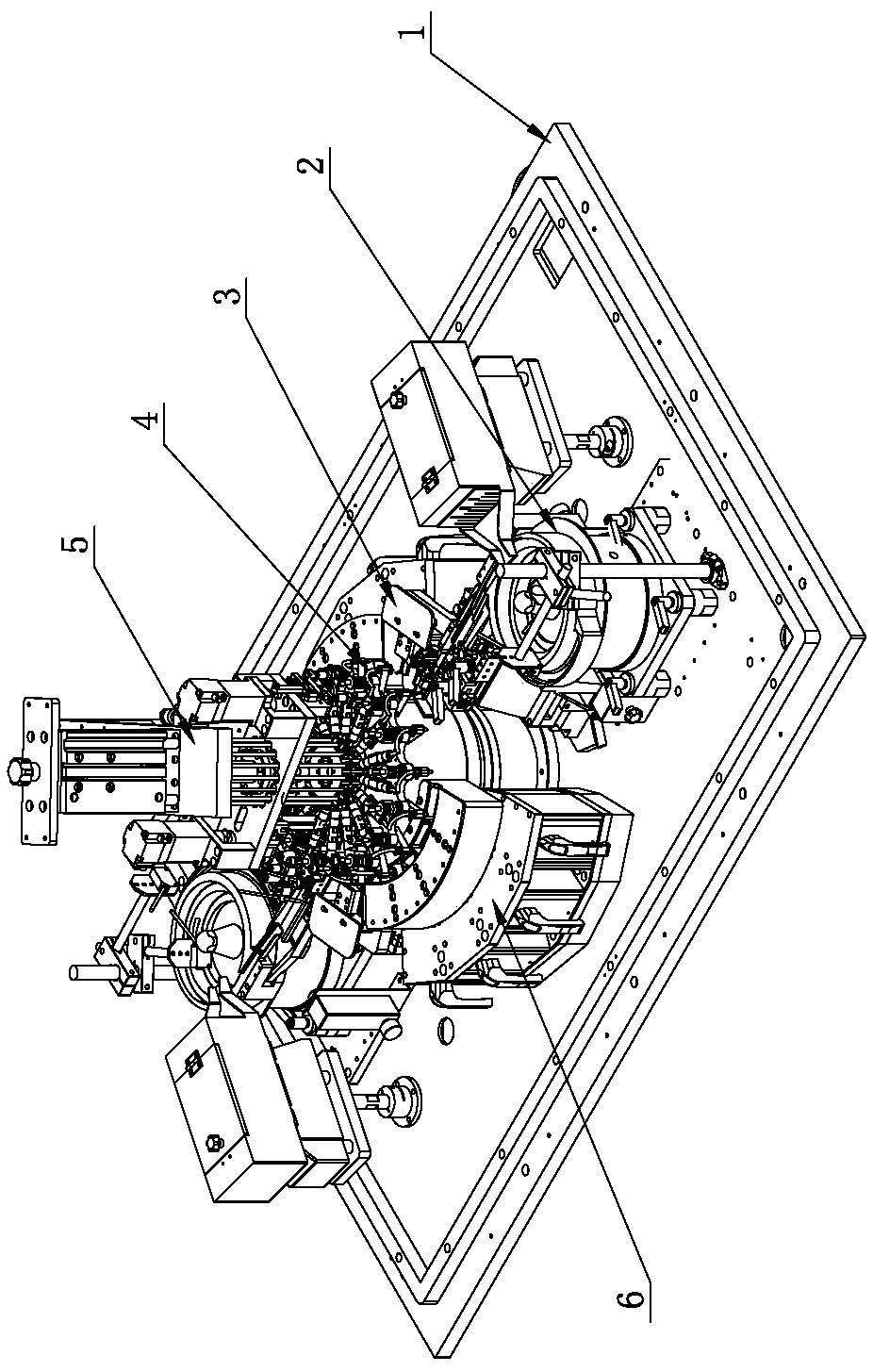
[0029] Such as Figure 1-13 A double-station chip testing and sorting machine shown includes a pair of feeding components 2, a pair of testing components 3, a turntable component 4, a pressing component 5 and a pair of distribution boxes 6 installed on the working platform 1. ;

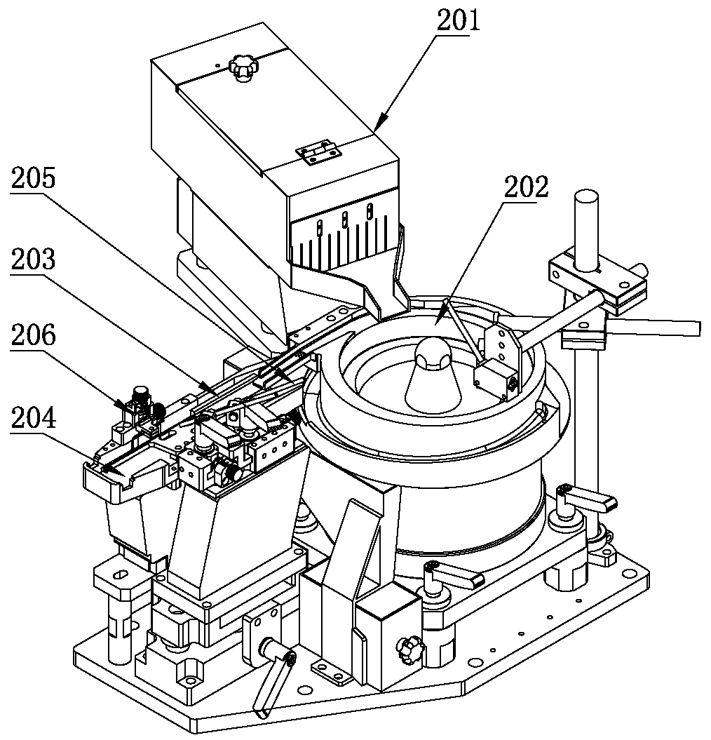
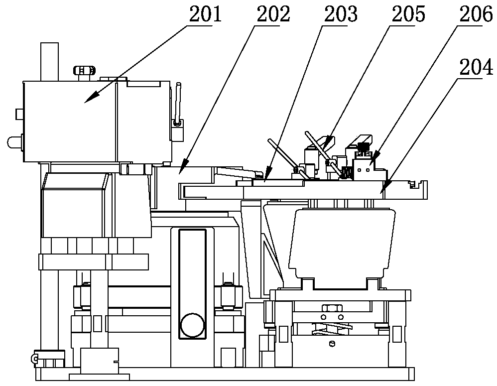
[0030] The feeding assembly 2 is used to transport the chip 7 to be tested into the testing assembly 3. The feeding assembly 2 includes a circular shock tray 202 that receives the chip 7 to be tested in the storage bin 201, and the outlet of the circular shock tray 202. The feed port is connected to the direct vibration feeding track 203, and the direct vibration recovery track 204 is arranged below the direct vibration feeding track 203. The discharge port of the direct vibration recovery track 204 is connected to the circular vibration feeding tray 202, and the end of the direct vibration feeding track 203 is connected to the turntable assembly. 4 docking, for the suction nozzle 402 on the turntabl...


PUM


Abstract

The invention discloses a dual-station chip test sorting machine. The dual-station chip test sorting machine comprises a pair of feeding assemblies, a pair of test assemblies, a rotating disc assembly, a pressing assembly, and a pair of material dividing boxes which are installed on a working platform. The feeding assemblies are used for conveying to-be-tested chips to the test assemblies; the test assemblies are used for testing the to-be-tested chips; the rotating disc assembly is used for taking out the to-be-tested chips in the feeding assemblies and conveying the to-be-tested chips to thetest assemblies for testing, and finally conveying the to-be-tested chips to the material dividing box for sorting; The pressing assembly is used for controlling a suction nozzle on the rotating discassembly to move up and down and absorb the to-be-tested chips; and the material dividing boxes are used for separately collecting the tested chips. According to the dual-station chip test sorting machine, during the vibration process of the direct shock feeding track, adhered chips are separated through a blowing pipe, and the overlapped to-be-tested chips are separated through the pressing needle, so that it is ensured that the suction nozzle on the rotating disassembly can accurately absorb the to-be-tested chips, thus the production efficiency is improved, and the dual-station chip test sorting machine can be used for chip testing.

Description

technical field [0001] The invention relates to a sorting machine, in particular to a chip testing and sorting machine. Background technique [0002] At present, most of the screening of qualified chips is not completed by using wafer test probe station. The wafer test probe tank is composed of a microscope, a probe holder, a workbench, a wafer holder, an electrical system and an interface display. It is equipped with a tester to complete the electrical parameter test and functional test of the wafer. Due to the limitations of its probes and dotting mechanism, the electrical parameters of this wafer test probe station can only be set to two levels (qualified products and unqualified products, red dots for unqualified products), and only those whose electrical parameters are lower than the set indicators It can be classified as waste as unqualified products, and the actual part of unqualified products can be classified as the next grade (good product or middle-class product)...

Claims


Application Information

Patent Timeline
IPC IPC(8): B07C5/34B07C5/02
Inventor 莫健陆军陈尔军郭文吉俊
Owner 扬州爱迪秀自动化科技有限公司
Learn More