

Medical infusion pump body and manufacturing method thereof
A manufacturing method and technology of infusion pumps, applied in the field of medical infusion pump body and its manufacturing, capable of solving problems such as difficult design, complex structure design, complex mold structure, etc.
- Summary
- Abstract
- Description
- Claims
- Application Information
AI Technical Summary
Problems solved by technology
Method used
Image

Examples
Embodiment Construction
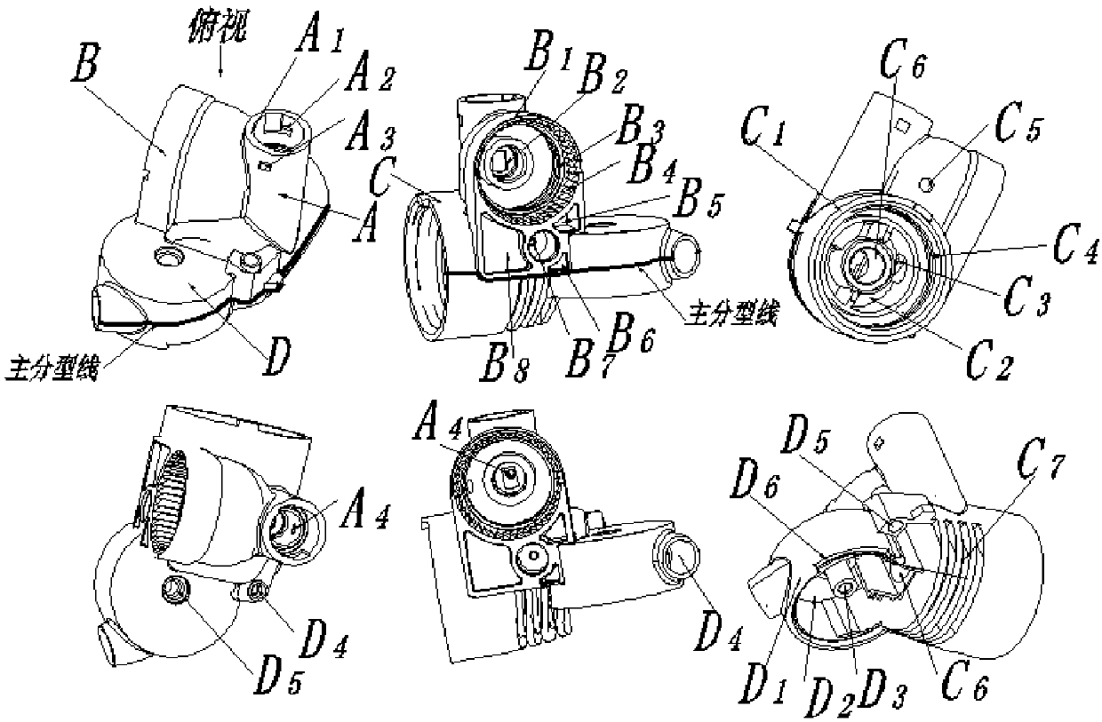
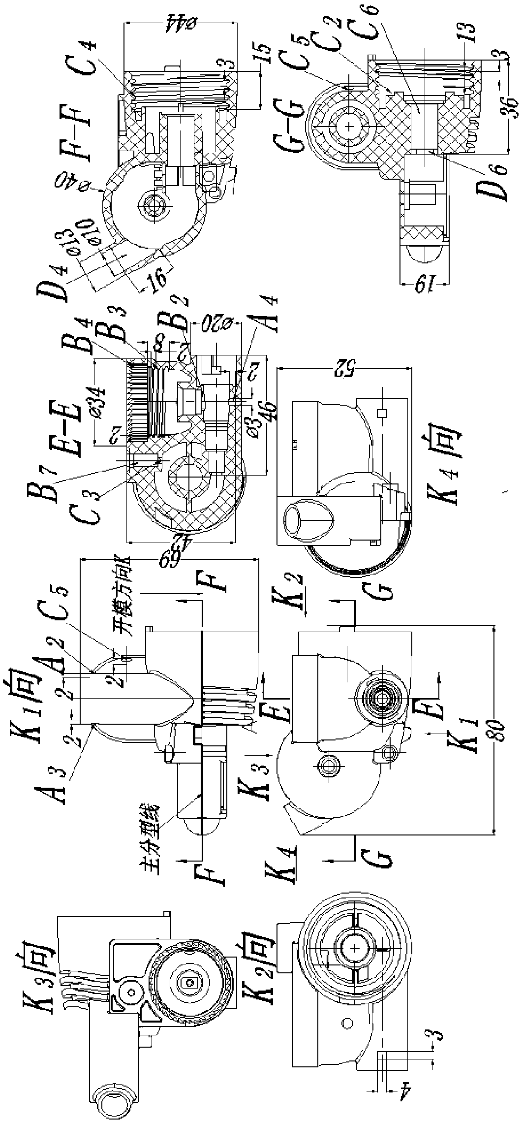
[0046] Figure 1-19 Shown is the relevant explanatory diagram of the present invention; the three-dimensional display diagram of the different orientations of the product structure aimed at by this mold is as follows figure 1 shown. The product is a thin shell, with an average wall thickness of 1.8mm, and the material is modified ABS+PC; the composition of the product is composed of four parts: liquid medicine inlet A, first outlet B, second outlet C, and third outlet D; Product classification design, in figure 1 Under the parting of the main parting line designed in , the mold release design of the product is the difficulty in the mold structure design of this product. These difficulties are as follows: A2 is designed on the basis of the cylindrical shell feature A1 of the liquid inlet A feature , A3, and A4 are three features that affect the demoulding of the product. A2, A3 are the side holes on the A1 cylinder, and A4 is a circular groove on the wall of the A1 cylinder h...
PUM
 Abstract
Description
Claims
Application Information