Check patentability & draft patents in minutes with Patsnap Eureka AI!

Self-powered luminescent deceleration strip

A speed bump, self-powered technology, applied in the direction of electrical components, electromechanical devices, electric components, etc., can solve the problem of speed bump energy waste and other issues

Pending Publication Date: 2019-06-21
SOUTHWEST JIAOTONG UNIV
View PDF0 Cites 2 Cited by
  • Summary
  • Abstract
  • Description
  • Claims
  • Application Information

AI Technical Summary

Problems solved by technology

[0004] The technical problem to be solved by the present invention is: the present invention provides a luminous speed bump that can supply power, which solves the problem mentioned in the prior art that the energy generated when the speed bump rises is not recovered, resulting in energy waste

Method used


Image

  • Self-powered luminescent deceleration strip
  • Self-powered luminescent deceleration strip
  • Self-powered luminescent deceleration strip

Examples


Embodiment Construction

[0019] The present invention will be described in detail below in conjunction with the accompanying drawings and specific embodiments.

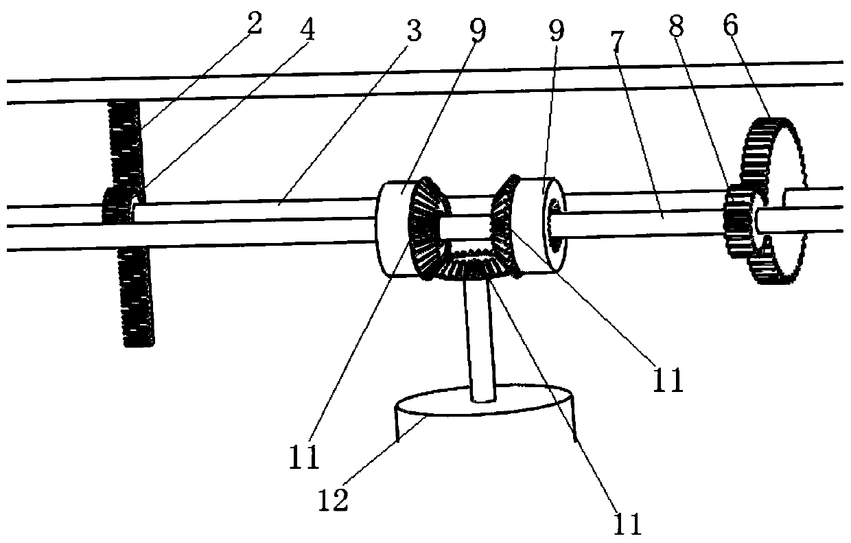
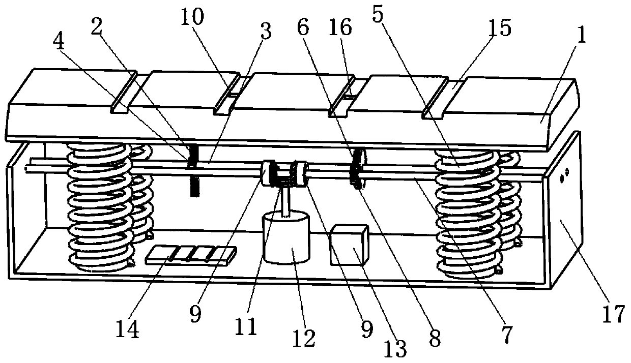
[0020] See attached figure 1 And attached figure 2 To describe the preferred embodiment of the present invention in detail, a self-powered luminous deceleration belt includes a rack 2 vertically installed on one end of the deceleration belt 1 close to the ground, and one end is installed on the end of the deceleration belt 1 close to the ground The spring 5, the other end of the spring 5 is installed on the bottom plate of the box body 17, and the first transmission shaft 3 and the second transmission shaft 7 are installed in the box body 17, and the first transmission shaft 3 is equipped with a A gear 4 meshed with the rack 2, and a large gear 6 capable of meshing with a pinion 8 installed on the second transmission shaft 7 is installed on the first transmission shaft 3, and on the second transmission shaft 7 is also installed There is a ...


PUM


Abstract

The invention relates to the field of road facilities, particularly to a self-powered luminescent deceleration strip. The self-powered luminescent deceleration strip comprises a rack vertically mounted on one end, close to the ground, of the deceleration strip, and a spring of which one end is mounted on the end, close to the ground, of the deceleration strip, the other end of the spring is mounted on the bottom plate of a box, the box is internally provided with a first transmission shaft and a second transmission shaft, the first transmission shaft is provided with a gear capable of being meshed with the rack, the first transmission shaft is provided with a large gear capable of being meshed with a pinion mounted on the second transmission shaft, the second transmission shaft is furtherprovided with a pair of internally meshing ratchet wheels which are oppositely mounted, each of the internally meshing ratchet wheel is provided with a bevel gear in a sleeving manner, and the bevel gears sleeving the internally meshing ratchet wheels are respectively meshed with bevel gears mounted on a generator shaft, electric energy generated by a generator is stored by a super-capacitor, thedeceleration strip circles through the pair of internally meshing ratchet wheels when moving up and down, thereby ensuring the bevel gears mounted on the generator to rotate toward the same direction,and the continuous generating of the generator is ensured.

Description

technical field [0001] The invention relates to the field of road facilities, in particular to a self-powered luminous speed bump. Background technique [0002] With the improvement of people's living standards, there are more and more vehicles on the road. At present, on the roads where the vehicles are concentrated, for the sake of safety, several deceleration belts will be set on the road to reduce the speed of the vehicles. Ordinary deceleration The belts are all fixed on the road. Although the vehicle can achieve the purpose of deceleration when passing the speed reduction belt, it consumes extra energy of the car and brings unnecessary energy waste. [0003] In order to use the speed bump to recycle the energy generated when the car decelerates, the invention patent application number CN2013104250444 provides an energy recovery device using the speed bump, including an energy collection part and an energy stable release part. The energy collection part includes a sprin...

Claims


Application Information

Patent Timeline
IPC IPC(8): E01F9/529E01F9/559H02K7/116H02K7/18
Inventor 刘建阳刘坚马乙峰仲成军王发宇吴小平
Owner SOUTHWEST JIAOTONG UNIV
Features
  • R&D
  • Intellectual Property
  • Life Sciences
  • Materials
  • Tech Scout
  • Unparalleled Data Quality
  • Higher Quality Content
  • 60% Fewer Hallucinations
Learn More