Self-resetting beam column friction energy dissipation joint structure and construction method thereof

A node structure, friction energy consumption technology, applied in the direction of buildings, building types, building components, etc., can solve the problems of serious node damage, large residual deformation, difficult control, etc., to achieve good energy consumption performance, simple structural form, mechanical Model explicit effects

Active Publication Date: 2019-06-21
HAINAN UNIVERSITY
View PDF9 Cites 26 Cited by
  • Summary
  • Abstract
  • Description
  • Claims
  • Application Information

AI Technical Summary

Problems solved by technology

[0004] However, it is difficult to control the damage mode and energy-dissipating parts of the traditional beam-column joints in the existing steel frame under earthquake action. Plastic hinges appear at the beam ends, and the joints are seriously damaged after the earthquake, with large residual deformation and difficult repair.

Method used


Image

  • Self-resetting beam column friction energy dissipation joint structure and construction method thereof
  • Self-resetting beam column friction energy dissipation joint structure and construction method thereof
  • Self-resetting beam column friction energy dissipation joint structure and construction method thereof

Examples


Embodiment 1

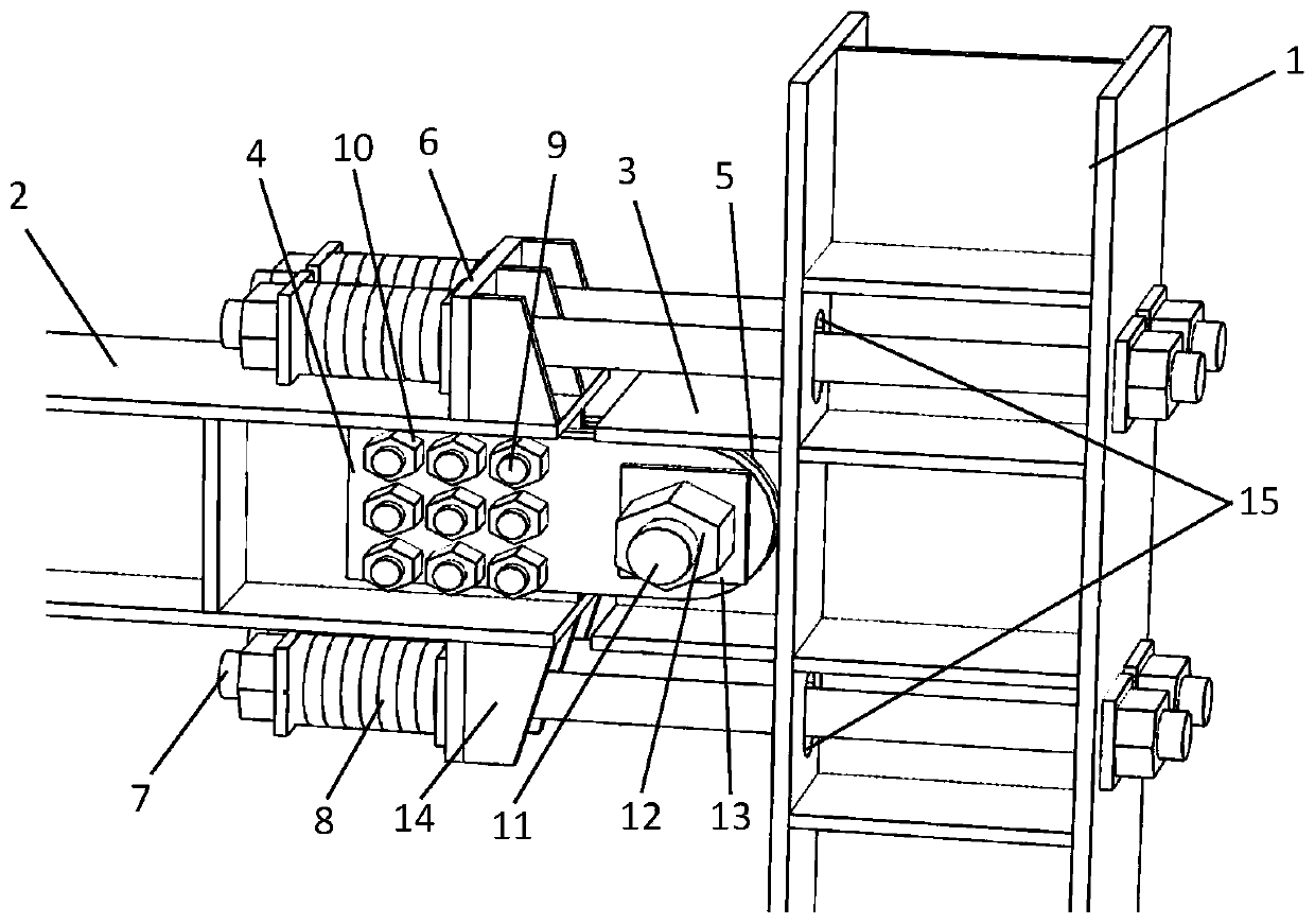
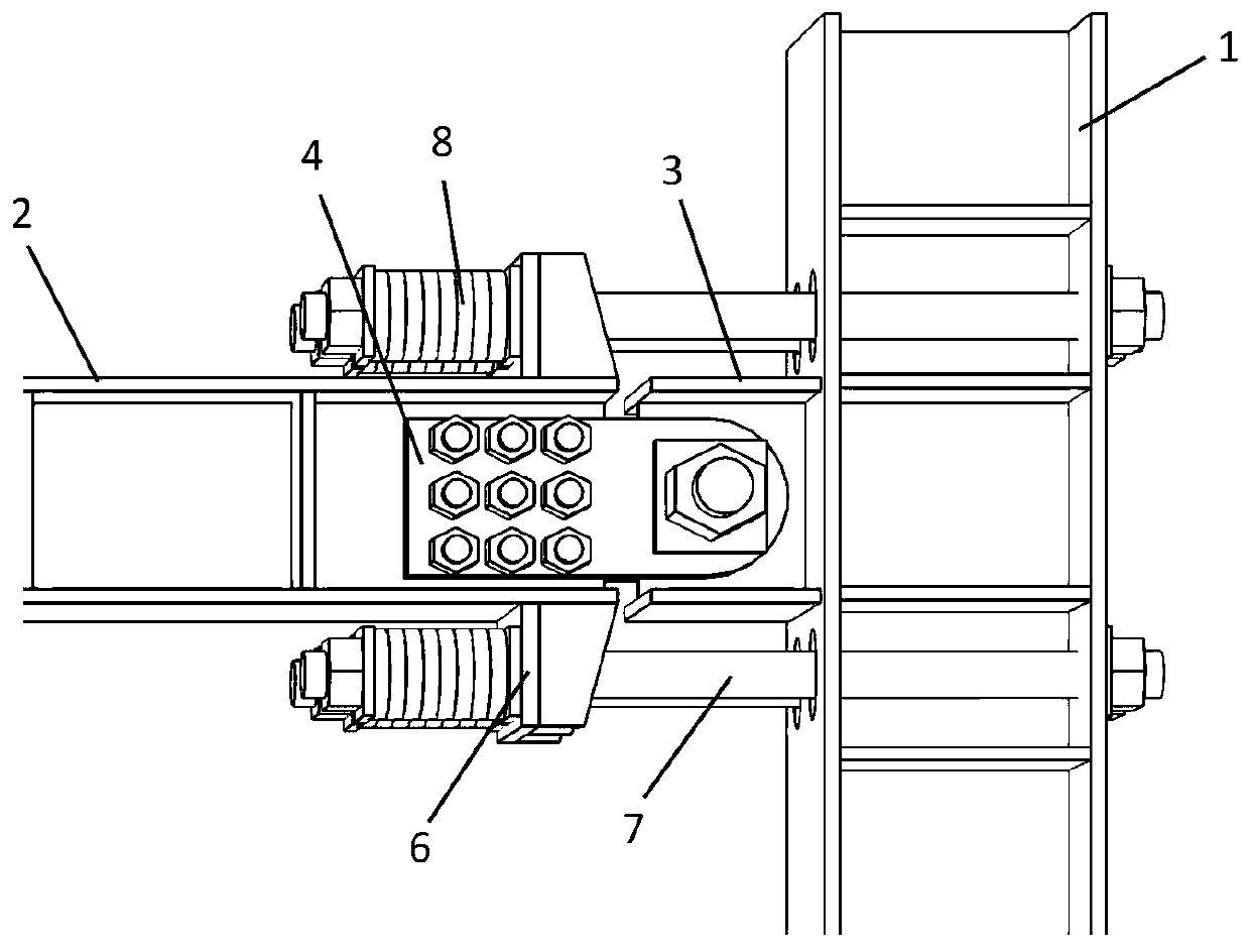
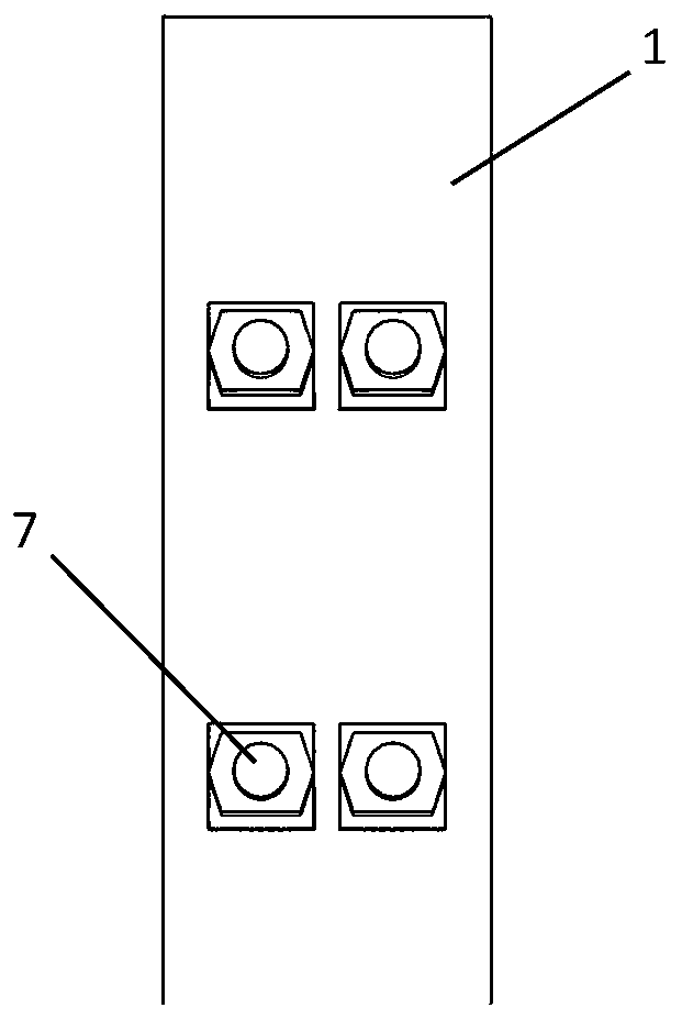
[0057] See attached figure 1 To attach Figure 4 , the embodiment of the present invention discloses a self-resetting beam-column friction energy-dissipating node structure, which is characterized in that it includes a steel column 1, an intermediate beam 2, a short beam 3, a connecting plate 4, a brass friction plate 5, and a spring baffle 6 , high-strength anchor rod 7 and disc spring 8;

[0058] The steel column 1 is arranged vertically, and the middle beam 2 is arranged horizontally;

[0059] The short beam 3 is located between the steel column 1 and the middle beam 2, one end of which is fixedly connected to the flange of the side wall of the steel column 1, and there is a gap between the middle beam 2 and the short beam 3;

[0060] One end of the connecting plate 4 is fixedly connected with the web of the intermediate beam 2, and the other end of the connecting plate 4 is hinged with the web of the short beam 3;

[0061] The brass friction plate 5 is arranged between ...

Embodiment 2

[0075] See attached Figure 5 , the embodiment of the present invention discloses a method for constructing a self-resetting beam-column frictional energy-dissipating node structure, which specifically includes the following steps:

[0076] S1. Foundation construction: Preliminarily determine the column network layout and beam-column dimensions of the frame where the node structure is located according to the functional requirements of the building structure, engineering geological conditions and conceptual design;


PUM


Abstract

The invention discloses a self-resetting beam column friction energy dissipation joint structure and a construction method thereof. The self-resetting beam column friction energy dissipation joint structure comprises a steel column, a middle beam, short beams, connecting plates, a brass friction plate, spring baffles, high-strength anchor rods and disc springs. One ends of the short beams are fixedly connected with the flanges of the side wall of the steel column, and a gap exists between the middle beam and the short beams; one ends of the connecting plates are fixedly connected with the webof the middle beam, and the other ends are hinged to the webs of the short beams; the brass friction plate is arranged between the connecting plates and the webs of the short beams; one ends of the high-strength anchor rods penetrate through the spring baffles, and the other ends of the high-strength anchor rods penetrate through the two flanges of the steel column and are fixed. The spring discsare sleeved on the high-strength anchor rod on one side, far away from the steel column, of the spring baffles. Structural construction is completed through basic construction, small earthquake testing, parameter selection, node performance design and large earthquake inspection. According to the invention, the formation of a plastic hinge of a traditional steel frame beam-column joint is effectively avoided, the beam column joint is not damaged or slightly damaged under the action of a large earthquake, and the post-earthquake joint can be put into use without repair.

Description

technical field [0001] The invention relates to the technical field of energy dissipation and shock absorption of building structures, in particular to a self-resetting beam-column frictional energy-dissipating node structure and a construction method thereof. Background technique [0002] At present, the traditional anti-seismic thinking takes protecting life as the primary goal, and prevents structures from collapsing under strong earthquakes through ductile design. This ductile design comes at the expense of allowing plastic deformation of the main stressed members of the structure. At the same time, the structure may be subjected to earthquakes stronger than the fortification intensity during use, which will also cause damage and residual deformation of the structure. In fact, earthquake disasters in recent years have shown that the number of building collapses and casualties in earthquakes has been effectively controlled, but the economic losses and social impacts caus...

Claims


Application Information

Patent Timeline
Patent Type & Authority Applications(China)
IPC IPC(8): E04B1/24E04B1/58E04B1/98E04H9/02
Inventor 陈云陈超
Owner HAINAN UNIVERSITY
Why Eureka
Try Eureka