
LED (Light-emitting diode) desk lamp with rotatable spreadlight lens

A technology of LED desk lamp and polarizing lens, which is applied in the field of LED desk lamp with rotatable polarizing lens, which can solve problems such as troubles, heat radiation of desk lamps, and affecting user's concentration, so as to achieve comfortable reading and writing and increase desktop space.

Inactive Publication Date: 2019-06-21
BENCHMARK SMART LIGHTING CO LTD
View PDF6 Cites 5 Cited by
  • Summary
  • Abstract
  • Description
  • Claims
  • Application Information

AI Technical Summary

Problems solved by technology

[0002] At present, most of the desk lamps on the market are centered on the vertical light source to emit light to the surroundings, and the light is brightest at the vertical point, so the desk lamp must be placed directly in front of or on the left and right of the workbench, and the center point of the light source is in front of the user's face; placing the desk lamp in this way Although it is bright, it also has many disadvantages. It is easy to cause the user's head to touch the desk lamp, or the heat of the desk lamp radiates to the person's head, which affects the user's concentration.
[0003] When the table lamp is turned on, the illuminance in the non-direct area will be far lower than that in the direct area. When using it, the user needs to adjust the position of the table lamp to meet the illuminance requirements in the lighting area, and the table lamp sometimes produces light under the action of external force. Some shifting, so periodic adjustments are required, which can be a hassle

Method used


Image

  • LED (Light-emitting diode) desk lamp with rotatable spreadlight lens
  • LED (Light-emitting diode) desk lamp with rotatable spreadlight lens
  • LED (Light-emitting diode) desk lamp with rotatable spreadlight lens

Examples


Embodiment Construction

[0017] In order to make the content of the present invention more clearly understood, the technical solutions in the embodiments of the present invention will be clearly and completely described below in conjunction with the drawings in the embodiments of the present invention.

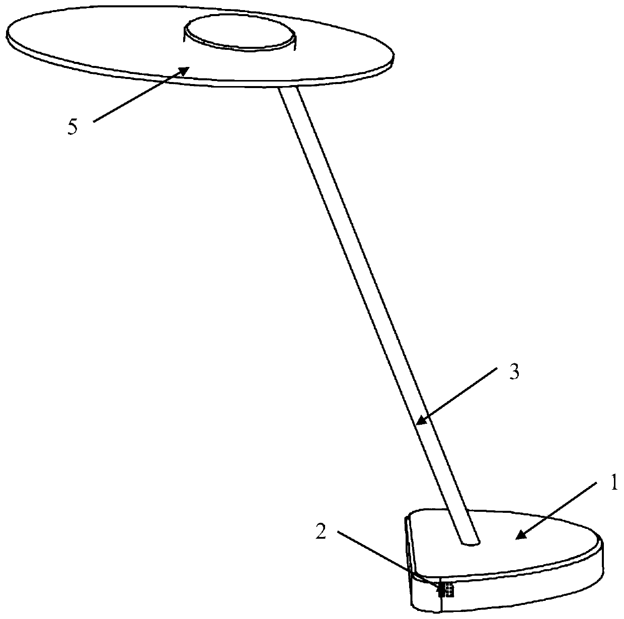
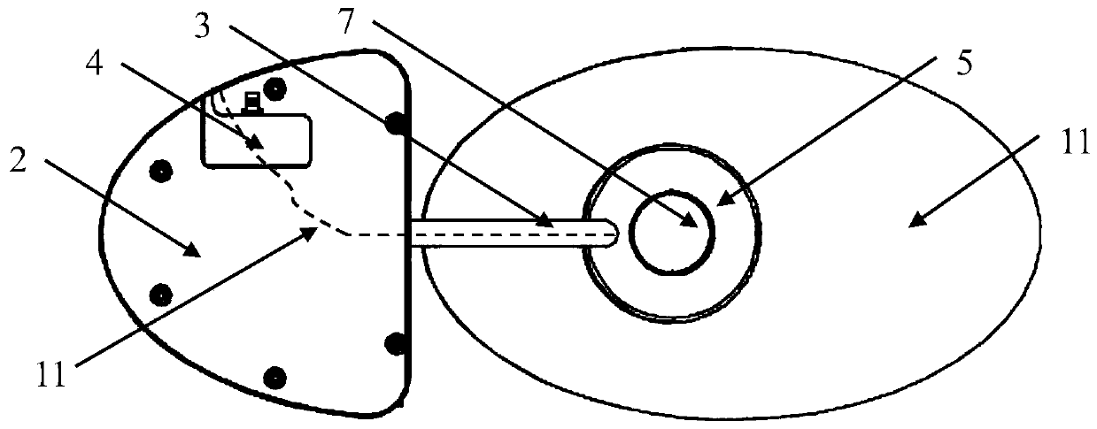
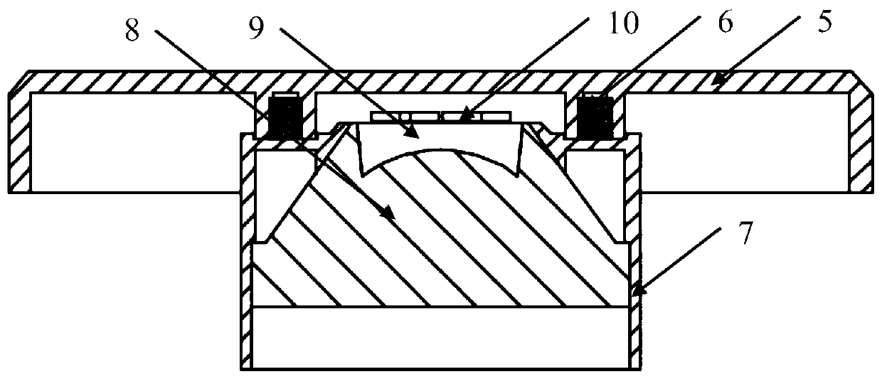
[0018] Such as Figure 1-Figure 3 As shown, a LED desk lamp with a rotatable polarizing lens includes a base 1 and a top cover 5. A light pole 3 is fixedly connected to the top surface of the base 1, and the other end of the light pole 3 is fixedly connected to the bottom surface of the top cover 5. The top cover 5 It can rotate around the light pole 3, and the rotation range is 0-150°; the side of the base 1 is provided with a switch 2, the bottom surface of the base 1 is provided with a battery slot, and a battery cover 4 is movably connected to the battery slot; the bottom surface of the top cover 5 The lens cover 7 is fixed through the bolt 6, the lens 8 is installed in the lens cover 7, the top o...


PUM


Abstract

The invention relates to a LED (Light-emitting diode) desk lamp with a rotatable spreadlight lens. The LED desk lamp comprises a base and a top cover, wherein a lamp pole is fixedly connected to the top surface of the base; the other end of the lamp pole is fixedly connected to the bottom surface of the top cover; a switch is arranged at the side edge of the base; a battery container is formed onthe bottom surface of the base; a battery cover is movably connected to the battery container; the bottom surface of the top cover is fixedly connected to a lens cover through a screw bolt; the lens is mounted in the lens cover; a lamp bead is mounted on the top end of the lens; and the lamp bead is connected to the switch through a power cord. According to the LED desk lamp with the rotatable spreadlight lens, through the spreadlight design of the lens, illumination in a non-direct irradiation region is enhanced; the illumination region of the desk lamp is increased again through a rotatablemode; the desk lamp can be freely placed to be far away from a work table; the problem of trouble caused by too short distance between the desk lamp and a work region is solved; a light ray irradiation region is changed by rotating the angle of the lens; others at rest cannot be influenced; meanwhile, desktop space is also increased; and reading and writing are more comfortable.

Description

technical field [0001] The invention relates to a rotatable polarizing lens LED desk lamp, in particular to a rotatable polarizing lens LED desk lamp. Background technique [0002] At present, most of the desk lamps on the market are centered on the vertical light source to emit light to the surroundings, and the light is brightest at the vertical point, so the desk lamp must be placed directly in front of or on the left and right of the workbench, and the center of the light source is in front of the user's face; placing the desk lamp in this way Although it is bright, it also has many disadvantages. It is easy to cause the user's head to touch the desk lamp, or the heat of the desk lamp radiates to the person's head, which affects the user's concentration. [0003] When the table lamp is turned on, the illuminance in the non-direct area will be far lower than that in the direct area. When using it, the user needs to adjust the position of the table lamp to meet the illumin...

Claims


Application Information

Patent Timeline
IPC IPC(8): F21S6/00F21V21/06F21V21/10F21V23/04F21V5/04F21V19/00F21V21/30F21V14/02F21Y115/10
Inventor 张群波
Owner BENCHMARK SMART LIGHTING CO LTD
Learn More