Chemical material finished product dehydration tank

A dehydration tank and material technology, applied in the direction of drying solid materials, non-progressive dryers, dryers, etc., can solve the problems of inability to dehydrate chemical materials and waste energy, save energy consumption, speed up dehydration, prevent heat The effect of air diffusion

Active Publication Date: 2019-06-21
双键化工(泰兴)有限公司
View PDF6 Cites 9 Cited by
  • Summary
  • Abstract
  • Description
  • Claims
  • Application Information

AI Technical Summary

Problems solved by technology

The invention is mainly used to solve the problem that the existing dehydration tank cannot completely dehydrate chemical materials and energy is wasted in the dehydration process

Method used


Image

  • Chemical material finished product dehydration tank
  • Chemical material finished product dehydration tank
  • Chemical material finished product dehydration tank

Examples


Embodiment Construction

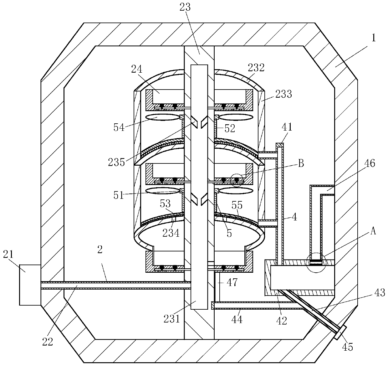
[0019] use Figure 1-Figure 4 A chemical material product dehydration tank according to an embodiment of the present invention is described as follows.

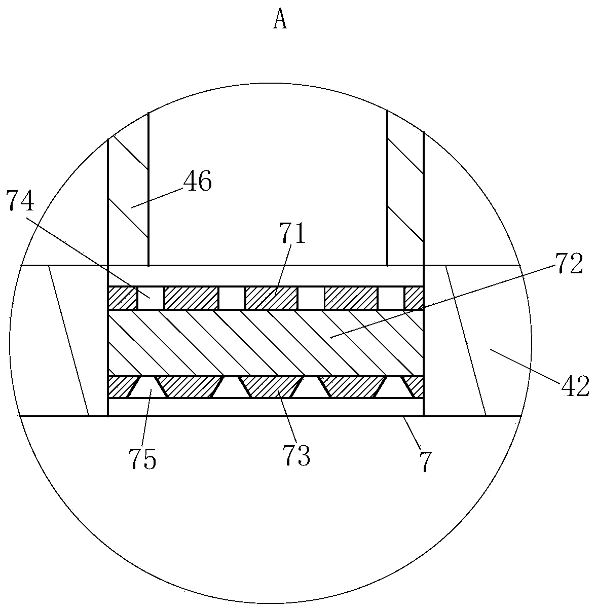
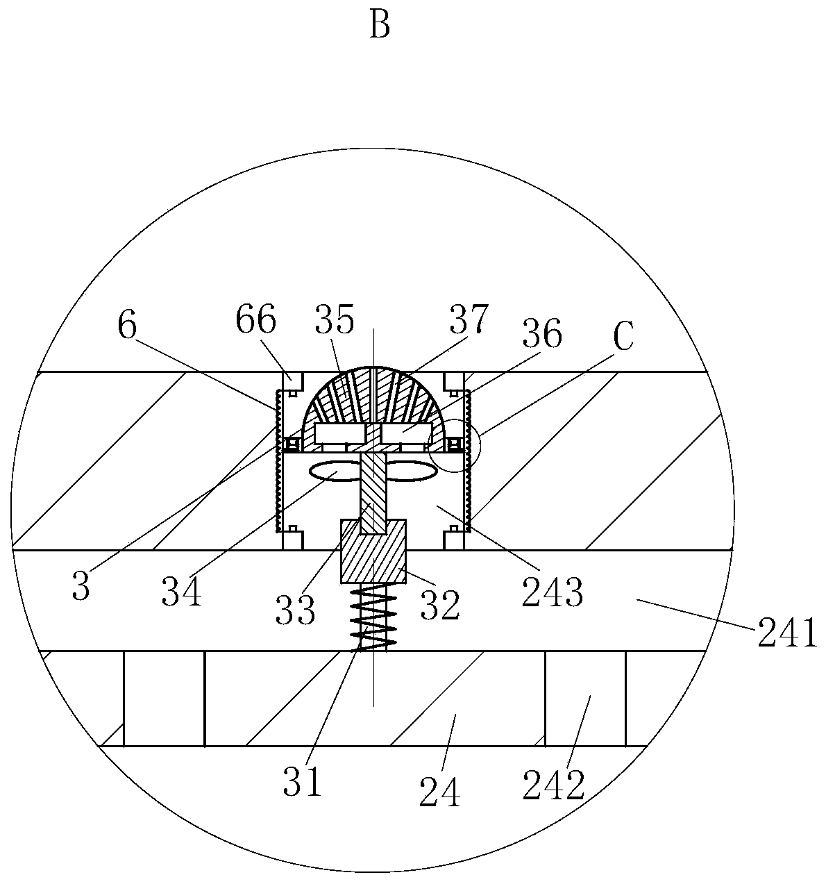
[0020] Such as Figure 1-Figure 4 As shown, a dehydration tank for finished chemical materials according to the present invention includes a frame body 1, an air transmission mechanism 2, a diffuser mechanism 3, an air outlet mechanism 4, an ash removal mechanism 5, a circulation mechanism 6 and a filter mechanism 7; The air delivery mechanism 2 comprises a hot air blower 21, an air delivery pipe 22 and a dispersing rod 23; the hot air blower 21 is fixedly mounted on the outer surface of the left end lower side of the frame body 1, and the right end of the hot air blower 21 is fixedly connected with an air delivery pipe 22; the air delivery pipe The right end of 22 is fixedly interspersed and connected in the lower end wall of the dispersing rod 23; the upper and lower ends of the dispersing rod 23 are vertically fixedly ins...


PUM


Abstract

The invention belongs to the technical field of chemical machinery, in particular to a chemical material finished product dehydration tank comprising a frame body, a gas conveying mechanism, a diffusing mechanism, an air outlet mechanism, a dust removing mechanism, a circulation mechanism and a filtering mechanism; the gas conveying mechanism comprises a hot air blower, a gas conveying pipe and adispersing rod; the upper and lower ends of the dispersing rod are vertically and fixedly mounted on the upper and lower walls of the inner end of the frame body, the dispersing rod is internally provided with a dispersing groove, and the outer surface of the dispersing rod is evenly and fixedly connected with flow guide plates; the flow guide plates are arranged to be in a round cover shape, theflow guide plates are sealed through a circular pipe, a leaking hole is formed in the wall of the flow guide plate at the lowest end, and placing frames are arranged below the flow guide plates; the placing frames are arranged in round pipes, the inner sides of the placing frames are evenly and fixedly connected to the outer surface of the dispersing rod, and the lower walls of the placing framesare internally provided with gas separation grooves. The chemical material finished product dehydration tank is mainly used for solving the problems that an existing dehydration tank cannot completelydehydrate chemical materials, and energy is wasted in the dehydration process.

Description

technical field [0001] The invention belongs to the technical field of chemical machinery, in particular to a dehydration tank for finished chemical materials. Background technique [0002] Dehydration is a chemical unit process and the reverse process of hydration. For simple hydrates, it is relatively easy to free water molecules from substance molecules. Generally, it only needs to be heated to evaporate water. For example, if sodium carbonate hydrate crystals are heated, they will be dehydrated and become sodium carbonate powder. But for the new substances that only partly combine with water molecules, dehydration must use catalysts or control other conditions, such as dehydration of ethanol to ethylene or ether, etc., and there is a dehydration tank in the chemical industry, which can dehydrate the materials produced in the chemical industry , in order to improve the material in chemical production from being oxidized, but the dehydration effect of the existing dehydra...

Claims


Application Information

Patent Timeline
Patent Type & Authority Applications(China)
IPC IPC(8): F26B11/18F26B21/00F26B25/00
Inventor 不公告发明人
Owner 双键化工(泰兴)有限公司
Why Eureka
Try Eureka