
Differential transformer type linear displacement sensor

A linear displacement sensor, differential transformer type technology, applied in the field of testing equipment, can solve the problems of increasing labor cost and economic cost, heavy maintenance workload, complicated debugging process, etc., so as to reduce debugging workload and reduce workload. , the effect of reducing the installation area

Pending Publication Date: 2019-06-21
西安西灵传感技术有限公司
View PDF0 Cites 0 Cited by
  • Summary
  • Abstract
  • Description
  • Claims
  • Application Information

AI Technical Summary

Problems solved by technology

[0002] At present, displacement sensors are installed on electro-hydraulic servo valves to measure the displacement of the valve core and provide parameters for system fault diagnosis and prevention. However, due to the parallel structure and large diameter of the traditional dual-redundancy displacement sensors, the installation position is limited. At the same time, the structure of the fixed coil used makes the debugging process more complicated, which increases the labor cost and economic cost
[0003] Although some displacement sensors of double-redundancy differential transformers adopt a series structure, their structure is a fixed ring structure, that is, the sensor body is fixed. In the early assembly and debugging process, it is necessary to adjust the position of the armature relative to the valve core to realize the zero position of the valve core. It is consistent with the zero output of the sensor, but because of the high pressure in the valve body, it needs to be disassembled and pressed repeatedly
Moreover, the spool of the electro-hydraulic servo valve will be worn after working for a period of time, which will also cause zero position offset. When the zero position is corrected, the electro-hydraulic servo valve needs to be disassembled again for adjustment. At the same time, due to the assembly and debugging environment of the electro-hydraulic servo valve The requirements are high and it needs to be carried out in the ultra-clean workshop, so the electro-hydraulic servo valve must be returned to the factory for processing, so that the maintenance workload is huge

Method used


Image

  • Differential transformer type linear displacement sensor
  • Differential transformer type linear displacement sensor
  • Differential transformer type linear displacement sensor

Examples


Embodiment 1

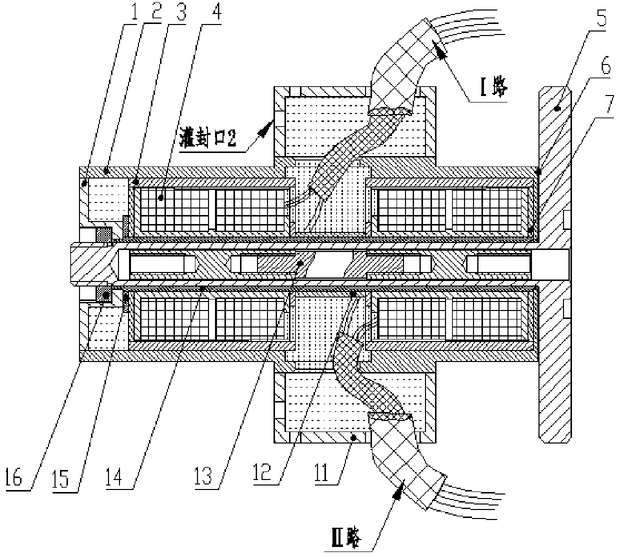
[0027] Such as Figure 1 to Figure 4 As shown, a differential transformer type linear displacement sensor includes a base 5, such as Figure 7 to Figure 8 As shown, the base 5 includes a flange 52, the flange 52 is provided with a rod body 51 coaxially connected with the flange 52, the flange 52 is provided with an inner hole 53 penetrating through the rod body 51, and the inner hole 53 is formed on the flange 52. The hole 53 is coaxially fitted with an armature assembly 13 connected to the spool of an external electro-hydraulic servo valve; the rod body 51 is sequentially fitted with a zero gasket 6 and a pipe body 14, and the pipe body 14 is coaxially A casing 2 is set, and the casing 2 is provided with a shielding gasket 7 and two skeleton components 4 in sequence, and the two skeleton components 4 are separated and positioned by a limit sleeve 12, and one end of the pipe body 14 that is away from the flange 52 The gasket 15, the end cap 1 and the tightening piece are also...


PUM


Abstract

The invention discloses a differential transformer type linear displacement sensor. The sensor comprises a base; the base comprises a flange; the flange is provided with a rod body coaxially connectedwith the flange; an inner hole passing through the rod body is formed in the flange; the inner hole coaxially sleeves an armature assembly; the rod body is sequentially sleeved with a zero-position spacer and a pipe body; the pipe body is coaxially sleeved with a housing; a shielding spacer and two frame assemblies are sequentially arranged in the housing; the frame assemblies are separated fromeach other and positioned through a limiting sleeve; one end of the pipe body, which is far away from the flange, is sequentially sleeved with a spacer, an end cover and a tightening component, wherein the spacer is closely attached to the frame assembly, and the tightening component is in threaded connection with the tail end of the rod body and is used for fixing the position of the end cover; the frame assemblies are connected with wires; and the wires are led out through wire outgoing holes formed in the housing. With the differential transformer type linear displacement sensor of the invention adopted, the requirement of miniaturization is satisfied; the influence of the armature on a valve core is minimized; and work efficiency is improved. The differential transformer type linear displacement sensor has the advantages of small debugging workload, high practicability and popularization value.

Description

technical field [0001] The invention belongs to the technical field of detection equipment, and in particular relates to a differential transformer type linear displacement sensor. Background technique [0002] At present, displacement sensors are installed on electro-hydraulic servo valves to measure the displacement of the valve core and provide parameters for system fault diagnosis and prevention. However, due to the parallel structure and large diameter of the traditional dual-redundancy displacement sensors, the installation position is limited. At the same time, the structure of the fixed coil used in it leads to a complicated debugging process, which increases labor costs and economic costs. [0003] Although some displacement sensors of double-redundancy differential transformers adopt a series structure, their structure is a fixed ring structure, that is, the sensor body is fixed. In the early assembly and debugging process, it is necessary to adjust the position of...

Claims


Application Information

Patent Timeline
IPC IPC(8): G01B7/02
Inventor 李继文李碧芯
Owner 西安西灵传感技术有限公司
Learn More