Rotary contact assembly and rotary switch

A technology of rotating contacts and components, applied in the direction of electric switches, electrical components, circuits, etc., can solve the problems of low assembly efficiency, low processing efficiency, and large volume, and achieve the goal of eliminating installation steps, improving processing efficiency, and simplifying processing procedures Effect

Pending Publication Date: 2019-06-21
舒森电子科技(常州)有限公司
View PDF0 Cites 1 Cited by
  • Summary
  • Abstract
  • Description
  • Claims
  • Application Information

AI Technical Summary

Problems solved by technology

[0004] The disadvantages of this structure include: 1. No matter how the machining accuracy is improved, it is difficult to achieve the same shape between the mandrel and the through hole of the insulating part. Only there is a gap between the outer wall of the mandrel and the inner wall of the through hole, and the mandrel and the through hole It is difficult to achieve synchronous rotation between the rotary contacts; and each rotary switch usually includes a plurality of rotary contacts arranged in sequence, and a plurality of mandrels nested in sequence, and each mandrel and the corresponding rotary contact The asynchronous rotation between the points will lead to poor synchronization between the upper and lower rotary contacts, resulting in poor sensitivity and other performance of the rotary switch as a whole; 2. The conductive part, insulating part and mandrel are all independently processed structures, which need to be assembled during assembly. The conductive part is first riveted to the insulating part, and then the insulating part is placed on the mandrel, which requires multiple mold openings, low processing efficiency and high processing cost; high labor costs and low assembly efficiency during assembly; 3. The insulating part and The mandrel is an independent structure processed separately, which requires more processing materials and high cost; and the volume after assembly is large, which is not conducive to the miniaturization of the rotary switch

Method used


Image

  • Rotary contact assembly and rotary switch
  • Rotary contact assembly and rotary switch
  • Rotary contact assembly and rotary switch

Examples


Embodiment Construction

[0031] The technical solution of the present invention will be further described below in conjunction with the accompanying drawings and through specific implementation methods.

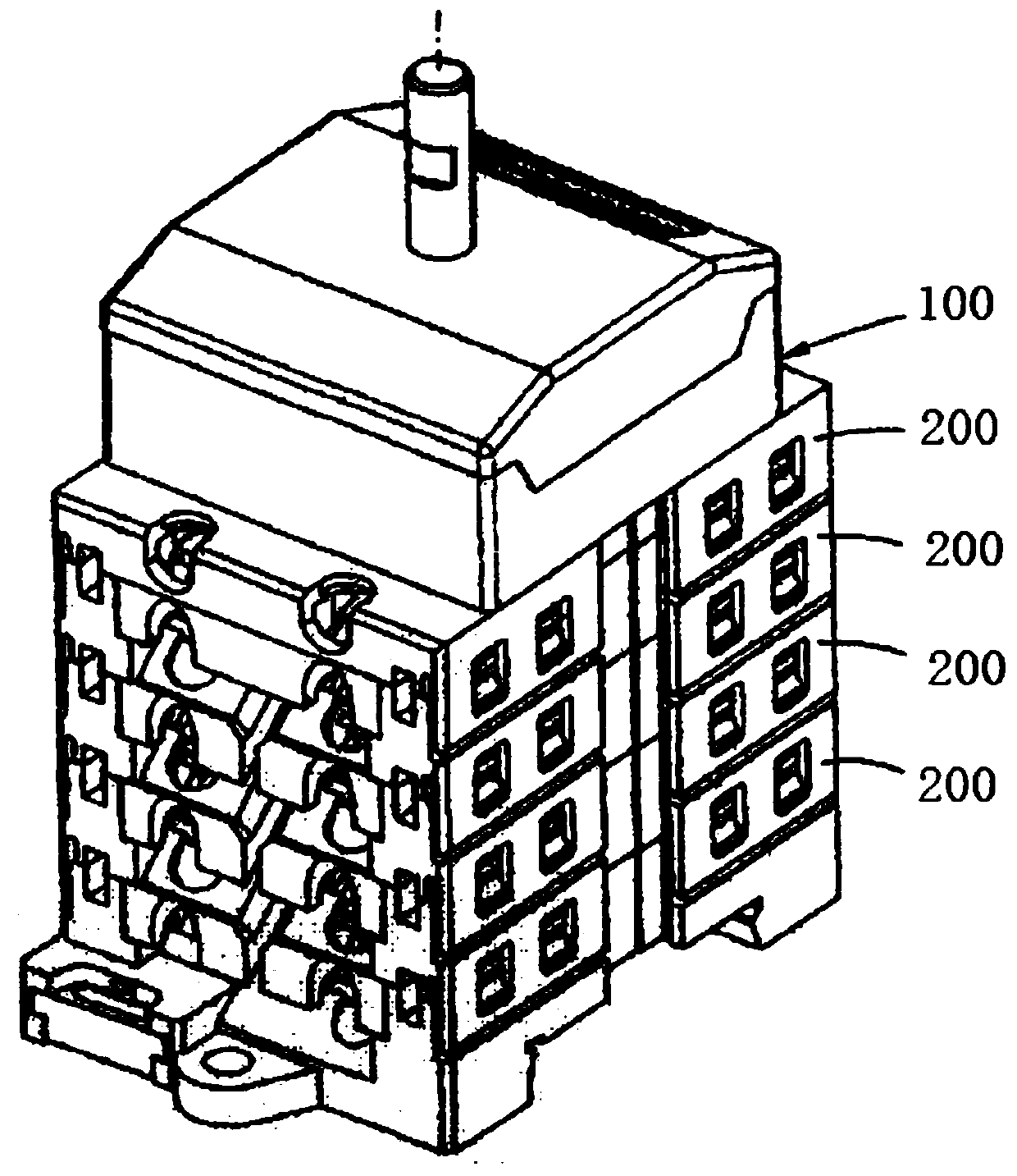
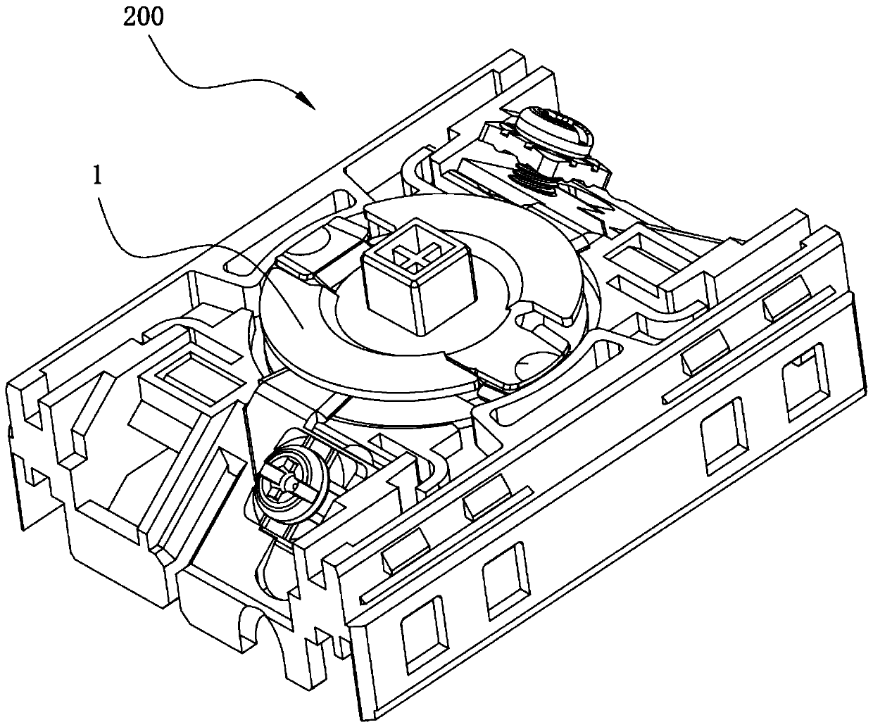
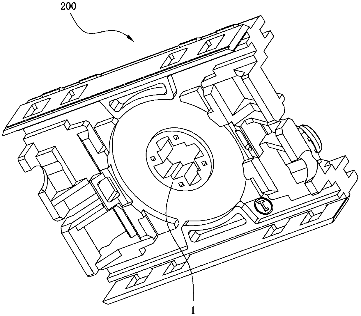
[0032] The embodiment discloses a rotary contact assembly and a rotary switch including the rotary contact assembly. Specifically, the rotary switch includes multiple sets of switch modules listed in sequence, such as figure 2 and image 3 As shown, a rotary contact assembly 1 is installed on each group of switch modules 200, wherein, figure 2 Shown is the front structure of the switch module, image 3 Shown is the rear structure of the switch module.

[0033] Such as Figure 4 to Figure 6 As shown, the rotary contact assembly includes an integrally formed insulating mandrel part, and a conductive part 11 is fixedly connected to the insulating mandrel part; wherein, the insulating mandrel part includes a cylindrical mandrel 12 and extends outward along the outer wall of the mandrel 12 The shee...


PUM


Abstract

The invention discloses a rotary contact assembly and a rotary switch, and belongs to the technical field of low-voltage electrical switches, and aims to solve the problems that the synchronism between an upper-layer rotating contact and a lower-layer rotating contact of an existing rotary switch is poor and the like. The rotary contact assembly comprises an integrally-formed insulating mandrel piece, wherein a conductive piece is fixedly connected to the insulating mandrel piece, wherein the insulating mandrel comprises a cylindrical mandrel and a sheet-shaped insulating part which extends outwards along the outer wall of the mandrel, and the end of the conductive piece protrudes out of the insulating part. The rotary switch comprises a plurality of groups of switch modules which are sequentially arranged, and each group of switch modules is provided with one rotary contact assembly. A gap is not formed between the rotary contact assembly and the mandrel and the insulating part of therotary switch, and between the mandrel and the conductive piece, and when the mandrel rotates, the conductive piece and the insulating part can be driven to rotate synchronously, so that the synchronism between the upper-layer rotary contact and the lower-layer rotary contact is improved, and the overall sensitivity and the like of the rotary switch are higher.

Description

technical field [0001] The invention relates to the technical field of low-voltage electrical switches, in particular to a rotary contact assembly and a rotary switch comprising the rotary contact assembly. Background technique [0002] A rotary switch is a device used to switch power, such as figure 1 As shown, it includes a rotation control module 100 and multiple sets of switch modules 200 arranged in sequence. Each set of switch modules 200 is equipped with rotary contacts, stationary contacts and mandrels for switching multiple currents. [0003] The existing rotary contact includes a conductive part and an insulating part that are riveted to each other. The insulating part is in the form of a sheet as a whole, and a through hole is opened in the middle of the sheet structure, and the mandrel passes through the through hole and is clamped with the insulating part. When working, the mandrel rotates, driving the insulating part to rotate, realizing the overall rotation ...

Claims


Application Information

Patent Timeline
IPC IPC(8): H01H19/10H01H19/14H01H19/64
Inventor 潘序之
Owner 舒森电子科技(常州)有限公司
Why Eureka
Try Eureka