Filtering antenna device

A filter antenna and device technology, applied in waveguide devices, antennas, antenna coupling, etc., can solve the problem of not being able to suppress out-of-band spurious signals well, filter antennas do not have the ability to resist out-of-band stray signals, and reduce filter antenna Work efficiency and other issues

Inactive Publication Date: 2019-06-21
AAC TECH NANJING
View PDF6 Cites 5 Cited by
  • Summary
  • Abstract
  • Description
  • Claims
  • Application Information

AI Technical Summary

Problems solved by technology

[0005] However, the filter antenna in the related art does not have a structure to resist out-of-band spurious signals, cannot suppre

Method used


Image

  • Filtering antenna device
  • Filtering antenna device
  • Filtering antenna device

Examples


Embodiment Construction

[0028] The following will clearly and completely describe the technical solutions in the embodiments of the present invention with reference to the accompanying drawings in the embodiments of the present invention. Obviously, the described embodiments are only some, not all, embodiments of the present invention. Based on the embodiments of the present invention, all other embodiments obtained by persons of ordinary skill in the art without making creative efforts belong to the protection scope of the present invention.

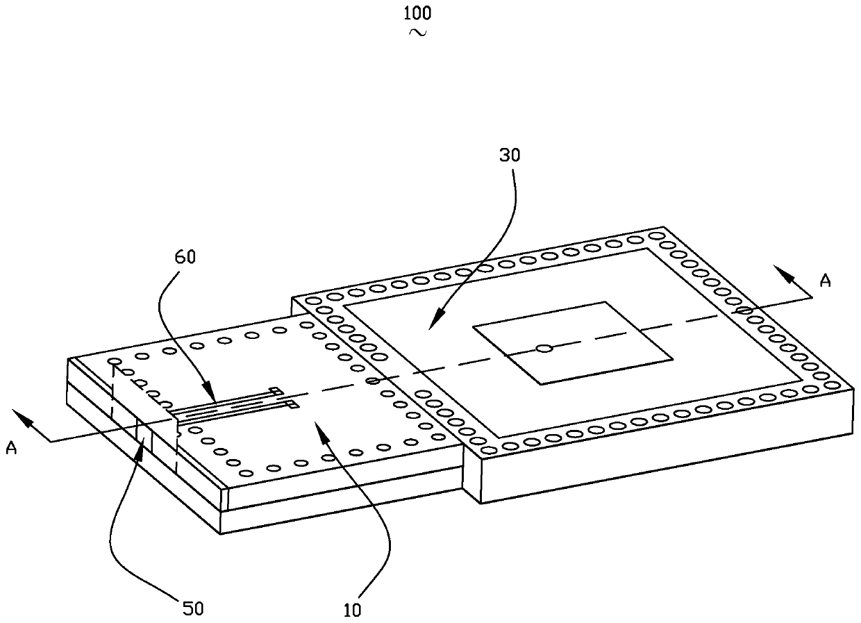
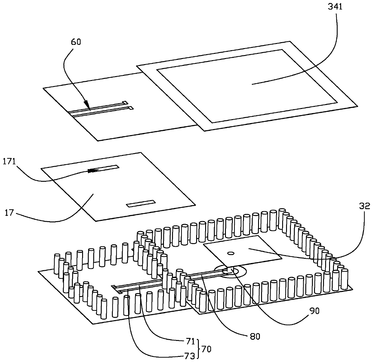
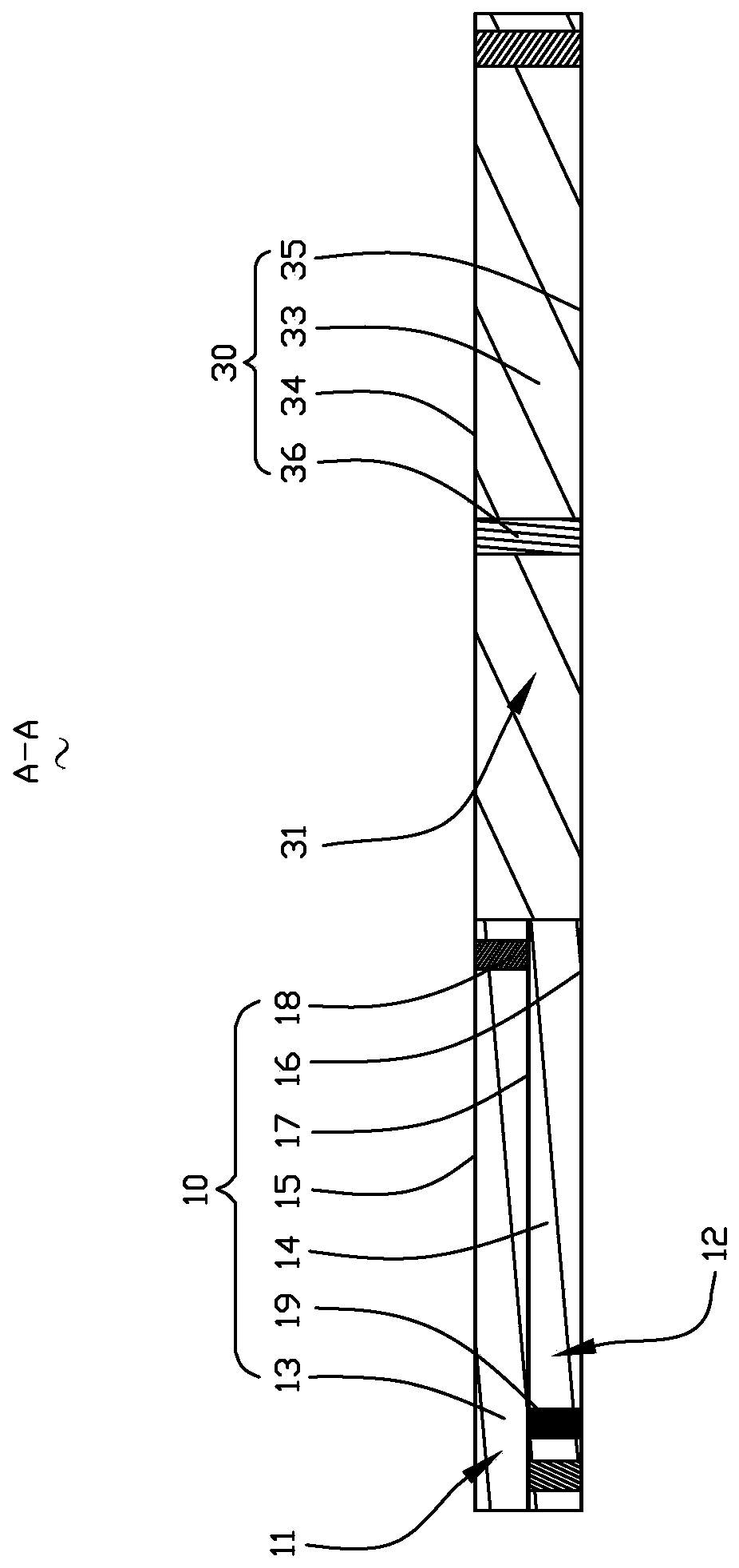
[0029] Please refer to Figure 1 to Figure 3 , the present invention provides a filtering antenna device 100, including an SIW filtering structure 10 and an SIW radiation structure 30 cascaded with the SIW filtering structure 10. Wherein, the SIW filter structure 10 includes a first resonant cavity 11 and a second resonant cavity 12 which are stacked up and down and communicated with each other. The SIW radiation structure 30 includes a back cavity 31 arrange...


PUM


Abstract

The invention provides a filtering antenna device. The filtering antenna device comprises an SIW filtering structure and an SIW radiation structure which is cascaded with the SIW filtering structure;the SIW filtering structure comprises a first resonant cavity and a second resonant cavity which are stacked in an up-down mode and communicate with each other; the SIW radiation structure comprises aback cavity and a metal patch; the back cavity is arranged side by side together with the first resonant cavity and the second resonant cavity, and communicates with the first resonant cavity and thesecond resonant cavity; the metal patch is contained in the back cavity; the filtering antenna device further comprises a feed port and a first coplanar waveguide which are arranged on one side, faraway from the back cavity, of the first resonant cavity, a second coplanar waveguide arranged on one side, close to the back cavity, of the second resonant cavity, a transmission line arranged in theback cavity and connected with one end of the second coplanar waveguide, and a probe connected with the transmission line and the metal patch; and one end of the first coplanar waveguide is connectedwith the feed port, and the other end of the first coplanar waveguide is opposite to the end part, far away from the transmission line, of the second coplanar waveguide. Compared with the prior art, the filtering antenna device provided by the invention can inhibit the interference of out-of-band stray signals to effectively reduce the surface wave loss.

Description

[0001] 【Technical field】 [0002] The invention relates to the field of microwave communication, in particular to a filtering antenna device used in the field of communication electronic products. [0003] 【Background technique】 [0004] With the rapid development of wireless communication systems, the size of wireless communication terminals is getting smaller and smaller while their functions are powerful. Therefore, the design of multifunctional components such as balun filters, power dividing filters, filter antennas, etc. has gradually become an inevitable trend. . Integrating the antenna and the filter can effectively reduce the loss of the system, improve the efficiency of the system and reduce the size of the system. [0005] However, the filter antenna in the related art does not have a structure to resist out-of-band spurious signals, cannot suppress out-of-band spurious signals well, and is easily interfered by surface waves, reducing the working efficiency of the f...

Claims


Application Information

Patent Timeline
IPC IPC(8): H01Q1/36H01Q1/38H01Q1/52H01Q15/00H01P1/207
CPCH01P1/2088H01Q9/045H01P1/20318H01Q1/38H01Q1/50
Inventor 买剑春邾志民
Owner AAC TECH NANJING
Why Eureka
Try Eureka