Cladding power stripping device and laser device

A power and cladding technology, which is applied in the direction of lasers, laser components, laser components, etc., can solve the problem that the power stripping of the cladding cannot meet the demand, and achieve the effect of reliable stripping and preventing the overheating of the optical fiber

Pending Publication Date: 2019-06-21
LASER FUSION RES CENT CHINA ACAD OF ENG PHYSICS
View PDF4 Cites 4 Cited by
  • Summary
  • Abstract
  • Description
  • Claims
  • Application Information

AI Technical Summary

Problems solved by technology

[0004] In view of this, the purpose of the embodiments of the present invention is to provide a cladding power stripping device and a laser to improve the existing cladding power stripping can not meet the demand and other problems

Method used


Image

  • Cladding power stripping device and laser device
  • Cladding power stripping device and laser device
  • Cladding power stripping device and laser device

Examples


no. 1 example

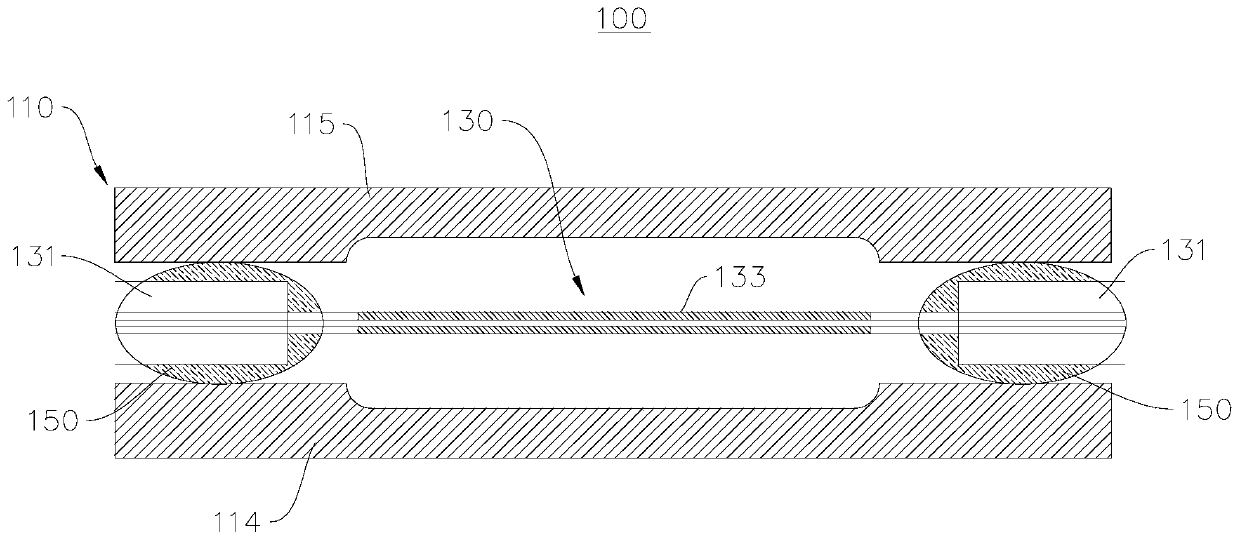
[0033] see figure 1 , this embodiment provides a cladding power stripping device 100 , and the cladding power stripping device 100 includes a cooling shell 110 , an optical fiber 130 and a glue layer 150 . The optical fiber 130 is disposed in the cooling housing 110 , and the optical fiber 130 is fixedly connected to the cooling housing 110 through the adhesive layer 150 .

[0034] The optical fiber 130 includes a bare fiber section 133 for cladding power stripping, and also includes a coating section 131 including a coating layer, and the coating section 131 is located on both sides of the bare fiber section 133 .

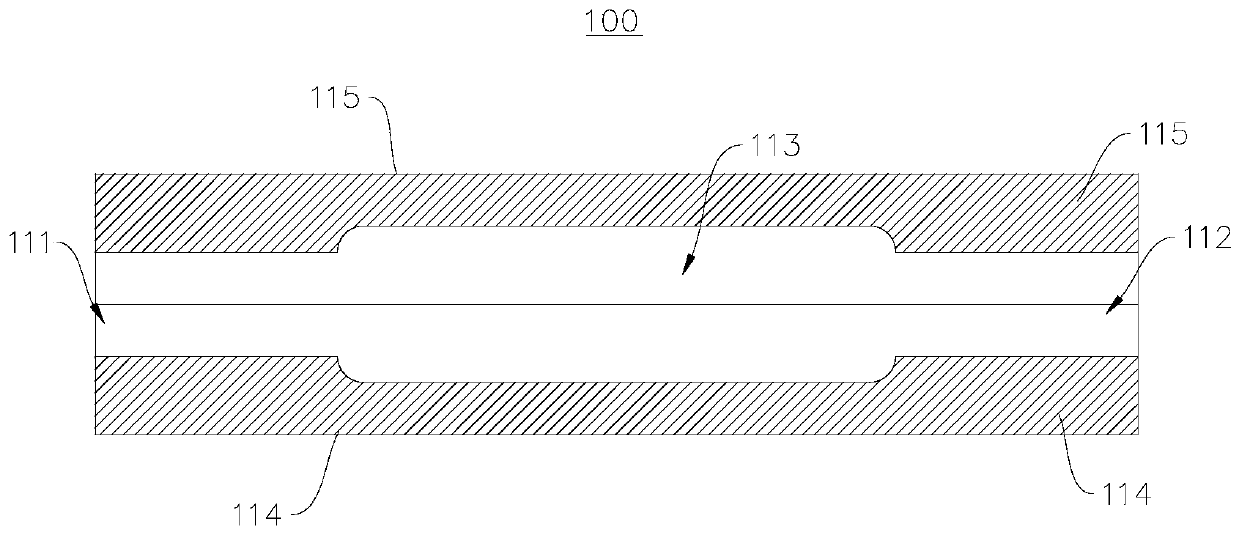
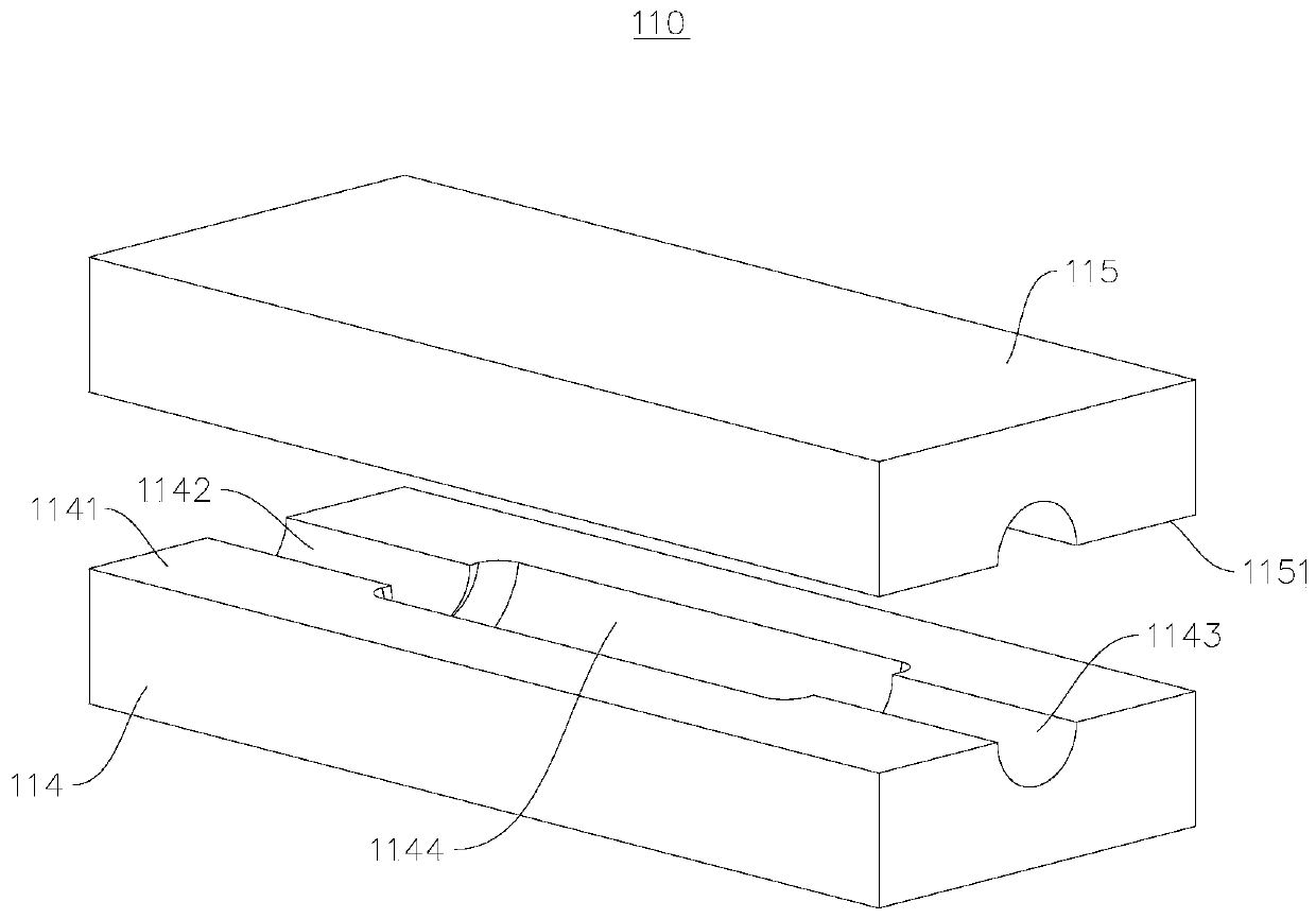
[0035] see figure 2 , the cooling housing 110 includes a cooling cavity 113, a first channel 111 and a second channel 112, the first channel 111 and the second channel 112 are respectively formed on both sides of the cooling cavity 113, the first channel 111 and the second channel 112 are connected with the cooling The cavity 113 communicates.

[0036] see i...


PUM


Abstract

The invention relates to the technical field of cladding light stripping, and specifically relates to a cladding power stripping device and a laser device. The cladding power stripping device comprises a cooling shell, an optical fiber and adhesive layers, wherein the cooling shell comprises a cooing cavity, a first passage and a second passage, the first passage and the second passage are communicated with the cooling cavity, and the interior of the cooling shell is filled with a cooling fluid; coating segments on two sides of the optical fiber are installed on the first passage and the second passage so that a bare fiber segment is placed inside the cooling cavity in a suspended mode; the coating segments are coated with the adhesive layers so that the coating segments on two sides are adhered with the first passage and the second passage in a sealing mode respectively. The coating segments of the optical fiber are adhered with the cooling shell by using the adhesive layers, on one hand, stray light returned back to an optical fiber coating layer is peeled, and the coating layer is prevented from being heated by return light; and on the other hand, the optical fiber coating layeris refrigerated effectively through the contact with the cooling shell, and the optical fiber is prevented from being overheated, so that the stripping cladding power can be improved.

Description

technical field [0001] The invention relates to the technical field of cladding light stripping, in particular to a cladding power stripping device and a laser. Background technique [0002] At present, cladding power stripping devices are mainly realized by optical glue coating or bare fiber surface microstructure treatment. The former is to smear the high refractive index polymer material on the bare fiber to refract the light in the fiber cladding to achieve the effect of cladding light stripping; the latter is to corrode or ablate or other treatments on the surface of the bare fiber way, creating an uneven surface that scatters cladding light out of the fiber. [0003] The biggest disadvantage of using the method of glue coating for light stripping is that the glue is not transparent enough and not heat-resistant enough, and the stripped waste light will be partially converted into heat, which will cause the risk of aging and burning of the light glue. The power of ten...

Claims


Application Information

Patent Timeline
Patent Type & Authority Applications(China)
IPC IPC(8): H01S3/04H01S3/042H01S3/067
Inventor 刘玙黄珊赵鹏飞唐选郭超
Owner LASER FUSION RES CENT CHINA ACAD OF ENG PHYSICS
Why Eureka
Try Eureka