Automatic feeding equipment for thin-wall punching member

A technology for stamping parts and equipment, which is applied in the field of automatic feeding equipment and feeding equipment for thin-walled stamping parts. Effects of impact, safety improvement, and control convenience

Active Publication Date: 2019-06-25
WUHAN UNIV OF TECH
View PDF7 Cites 1 Cited by
  • Summary
  • Abstract
  • Description
  • Claims
  • Application Information

AI Technical Summary

Problems solved by technology

[0002] In industrial applications, thin-walled stamping parts are very common processed parts. At present, in actual production, it mainly relies on manual loading and positioning processing. There are two problems in manual loading: 1. The processing time of manual loading cannot be maintained Constant, may affect subsequent processing
2. The processing process relies heavily on manpower, and people are in direct contact with the stamping machine tool. The safety performance is not high, and the waste and burrs generated by stamping parts are likely to cause harm to the health of workers.

Method used


Image

  • Automatic feeding equipment for thin-wall punching member
  • Automatic feeding equipment for thin-wall punching member
  • Automatic feeding equipment for thin-wall punching member

Examples


Embodiment Construction

[0025] In order to better understand the present invention, the present invention will be further described below in conjunction with the accompanying drawings and specific embodiments.

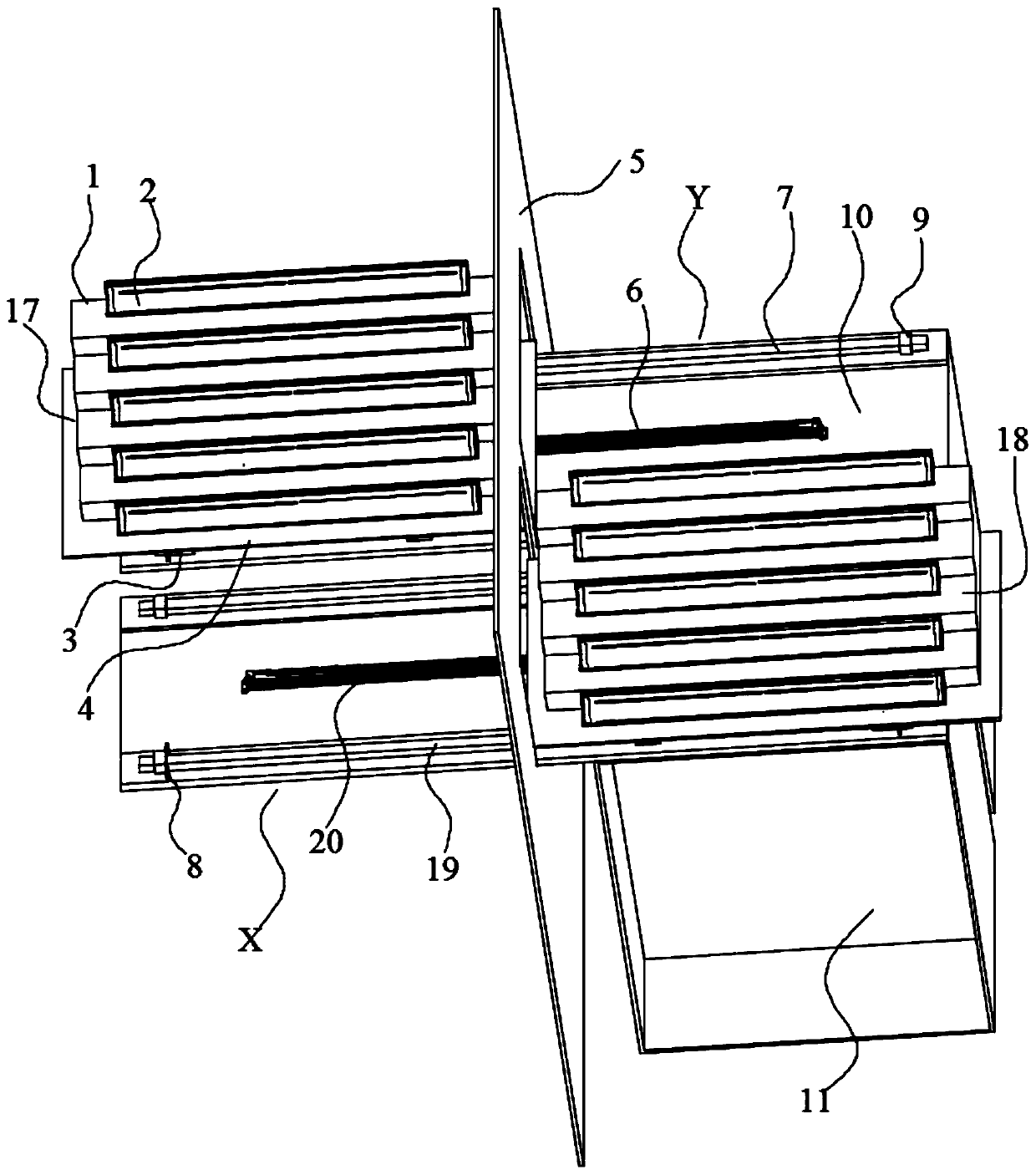
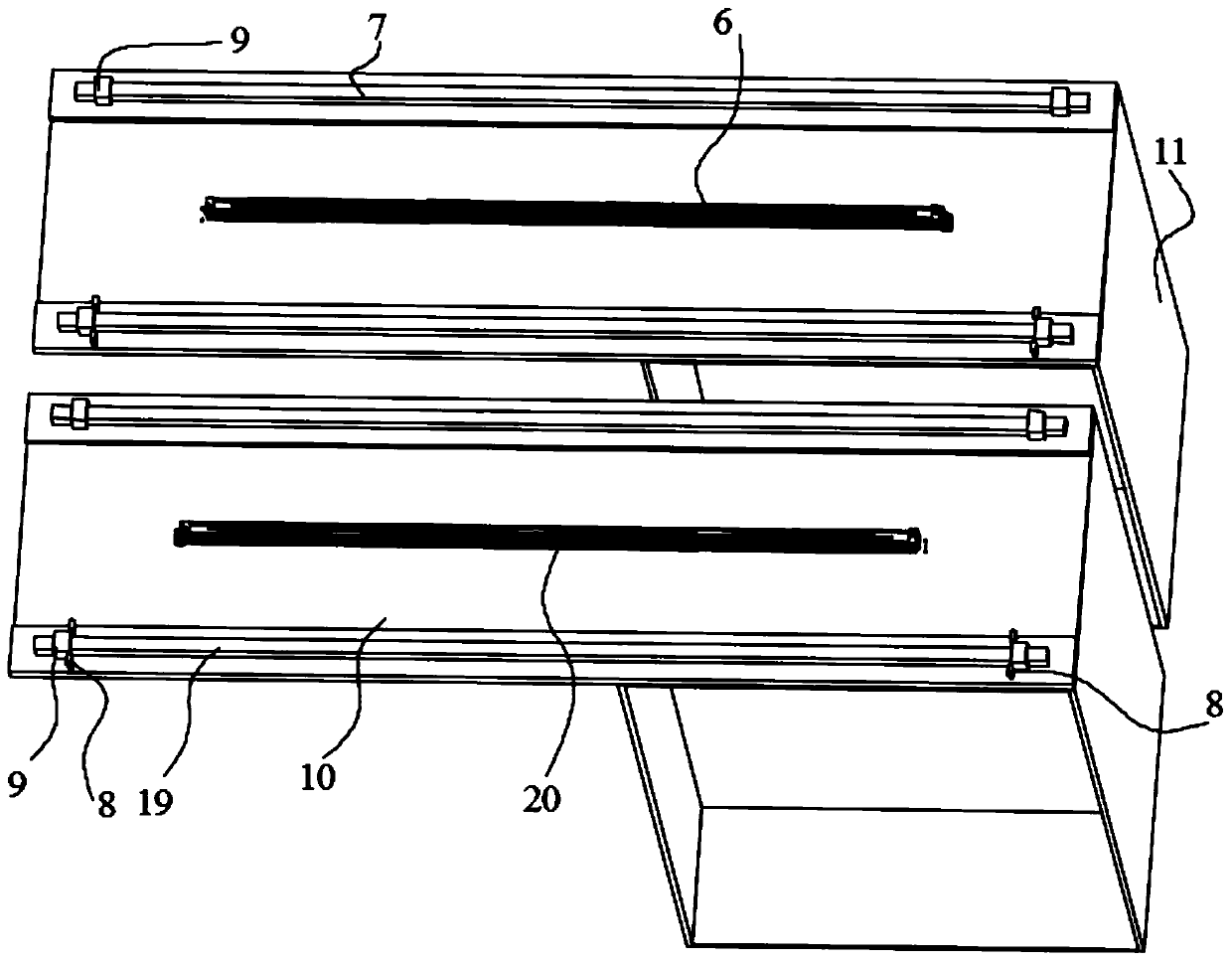
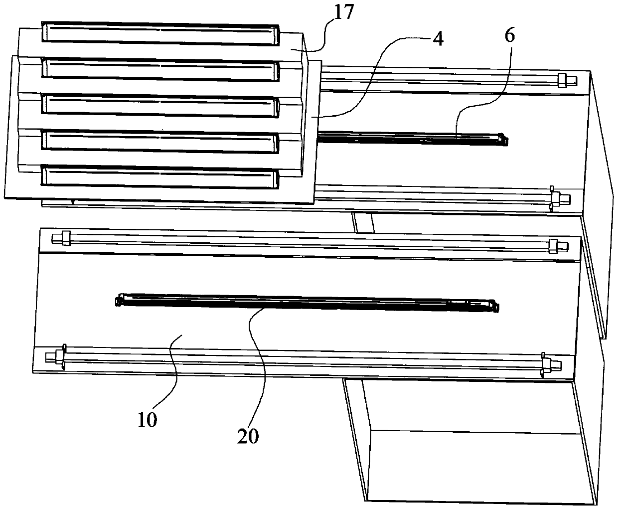
[0026] Such as Figure 1 to Figure 5 As shown, an automatic feeding device for thin-walled stampings includes a trapezoidal table 1, a positioning fixture 2, a slider 3, a pallet 4, a shield 5, a rodless cylinder, guide rails, a through-beam photoelectric sensor 8, Limit stopper 9, bottom support 10, base 11. Wherein the bottom bracket 10 is fixedly installed on the base 11 to form a workbench, and the trapezoidal table 1 and the positioning fixture 2 thereon form a tooling for placing workpieces. This embodiment has two toolings, which are tooling A 17 and tooling B 18 respectively. A 17 is installed on the tooling platform through the rodless cylinder M 6, and the tooling B 18 is installed on the workbench through the rodless cylinder N 20. The rodless cylinder M6 and the rodless cylinder ...


PUM


Abstract

The invention discloses automatic feeding equipment for a thin-wall punching member. The equipment comprises a working platform and two fixtures, each fixture is composed of a trapezoidal table and multiple positioning fixtures which are installed on the trapezoidal table, the working platform is divided into a working area and a material preparing area according to front and rear sequence, the two fixtures are installed on the working platform through two parallel rodless air cylinders, and vent holes formed in the two sides of the two rodless air cylinders are crossedly and serially connected to allow the two rodless air cylinders to maintain synchronous incongruous motion. The equipment has the advantages that the fixtures can be driven to move back and forth between the working area and material preparation area on the working platform through the rodless air cylinders, and the fixtures are installed on the working platform through a guiding rail sliding block structure. The construction of the feeding equipment is simple, the yield rate, quality, precision and efficiency are allowed to be greatly improved compared with manual feeding, processing, operating, controlling and using are allowed to be more convenient and simpler, and the safety performance of working is greatly improved.

Description

technical field [0001] The invention belongs to the field of numerical control processing and relates to a feeding device, in particular to an automatic feeding device for thin-wall stamping parts. Background technique [0002] In industrial applications, thin-walled stamping parts are very common processing parts. At present, in actual production, it mainly relies on manual loading and positioning processing. There are two problems in manual loading: 1. The processing time of manual loading cannot be maintained Constant, may affect the subsequent processing. 2. The processing process relies heavily on manpower, and people are in direct contact with the stamping machine tool. The safety performance is not high, and the waste and burrs generated by stamping parts are likely to cause harm to the health of workers. In order to change the existing problems, we can start from the following three aspects: 1. By analyzing the material of the part, the original surface quality of t...

Claims


Application Information

Patent Timeline
Patent Type & Authority Applications(China)
IPC IPC(8): B21D43/00B21D43/02B21C51/00
Inventor 吴超群胡智杰
Owner WUHAN UNIV OF TECH
Why Eureka
Try Eureka