Cutting equipment for leather

A kind of equipment and leather technology, applied in the field of leather cutting equipment, can solve the problems of easy chemical damage to the human body, rough leather, etc., and achieve the effect of simple structure and convenient operation

Inactive Publication Date: 2019-06-25
杭州奇伶服饰有限公司
View PDF5 Cites 2 Cited by
  • Summary
  • Abstract
  • Description
  • Claims
  • Application Information

AI Technical Summary

Problems solved by technology

[0002] Leather is denatured and non-perishable animal skin obtained through physical and chemical processing such as depilation and tanning. Leather is composed of natural protein fibers tightly woven in three-dimensional space. There is a special grain layer on the surface with natural grain patterns. And luster, feel comfortable, the leather industry covers the main industries such as tanning, shoemaking, leather clothing, leather goods, fur and its products, as well as supporting industries such as leather chemical industry, leather hardware, leather machinery, accessories, etc., which is very important in leather processing. Part of the leather cutting technology is also constantly developing, but there are still many places where the leather processing relies on the mixed production of backward machinery and manual labor. Due to the addition of a large number of chemicals in the leather processing process, the leather processing process is easy to The human body produces chemical damage, and the leather cut out by rough production machinery is relatively rough, and many places need to be cut and polished again manually. Therefore, it is necessary to use a laser for precise cutting. The cut is equipped with a low-pressure vacuum device to ensure that the cutting surface is flat. Devices for Machining Accuracy

Method used


Image

  • Cutting equipment for leather
  • Cutting equipment for leather
  • Cutting equipment for leather

Examples


Embodiment Construction

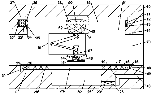
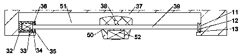
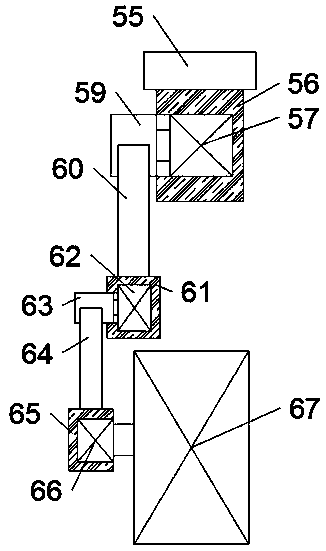
[0013] Combine below Figure 1-4 The present invention is described in detail, and for convenience of description, the orientations mentioned below are now stipulated as follows: figure 1 The up, down, left, right, front and back directions of the projection relationship itself are the same.

[0014] refer to Figure 1-4 , a kind of cutting equipment for leather according to the embodiment of the present invention, comprises device box 10, and described device box 10 is provided with lateral displacement chamber 37, and the bottom of described lateral displacement chamber 37 is communicated with longitudinal displacement chamber. Cavity 51, the horizontal displacement chamber 37 and the longitudinal displacement chamber 51 are provided with two sets of displacement devices perpendicular to each other, the displacement device includes a cutting device base 40, and the cutting device base 40 is provided with Drive cavity 50 and power cavity 38, described power cavity 38 and dr...


PUM


Abstract

The invention discloses cutting equipment for leather. The cutting equipment comprises a device box body, wherein a transverse displacement cavity is formed in the device box body, a longitudinal displacement cavity is in communication below the transverse displacement cavity, and two vertical displacement devices which are perpendicular to each other are arranged in the transverse displacement cavity and the longitudinal displacement cavity. The cutting device is provided with a cutting device base, the cutting device base is internally provided with a driving cavity and a power cavity, a displacement shaft is arranged in the driving cavity and the power cavity in a sliding mode, the flow speed of the air flow in an air inlet is accelerated by starting an exhaust fan of a low-pressure conveying device, the air pressure in a through hole of a conveying belt is reduced and even close to the vacuum, so that the leather needing to be machined can be stabilized on the machining plane, thevertical displacement shaft ensures flexible movement of the cutting device base, and the horizontal position of the cutting device base can be conveniently controlled through a coordinate axis.

Description

technical field [0001] The invention relates to the technical field of leather cutting, in particular to a cutting device for leather. Background technique [0002] Leather is denatured and non-perishable animal skin obtained through physical and chemical processing such as depilation and tanning. Leather is composed of natural protein fibers tightly woven in three-dimensional space. There is a special grain layer on the surface with natural grain patterns. And luster, feel comfortable, the leather industry covers the main industries such as tanning, shoemaking, leather clothing, leather goods, fur and its products, as well as supporting industries such as leather chemical industry, leather hardware, leather machinery, accessories, etc., which is very important in leather processing. Part of the leather cutting technology is also constantly developing, but there are still many places where the leather processing relies on the mixed production of backward machinery and manual...

Claims


Application Information

Patent Timeline
Patent Type & Authority Applications(China)
IPC IPC(8): C14B5/00C14B17/06
Inventor 余丹丹
Owner 杭州奇伶服饰有限公司
Why Eureka
Try Eureka