Leveling device for automobile test ramp gravel
A car test and ramp technology, which is applied in the direction of roads, roads, road repairs, etc., can solve the problems of flat gravel, insufficient precision, and occupation of tractors on car test ramps, and achieve accurate and reliable test results. The effect of quality level
- Summary
- Abstract
- Description
- Claims
- Application Information
AI Technical Summary
Problems solved by technology
Method used
Image

Examples
Embodiment Construction
[0050] The present invention will be further described below in conjunction with the accompanying drawings.
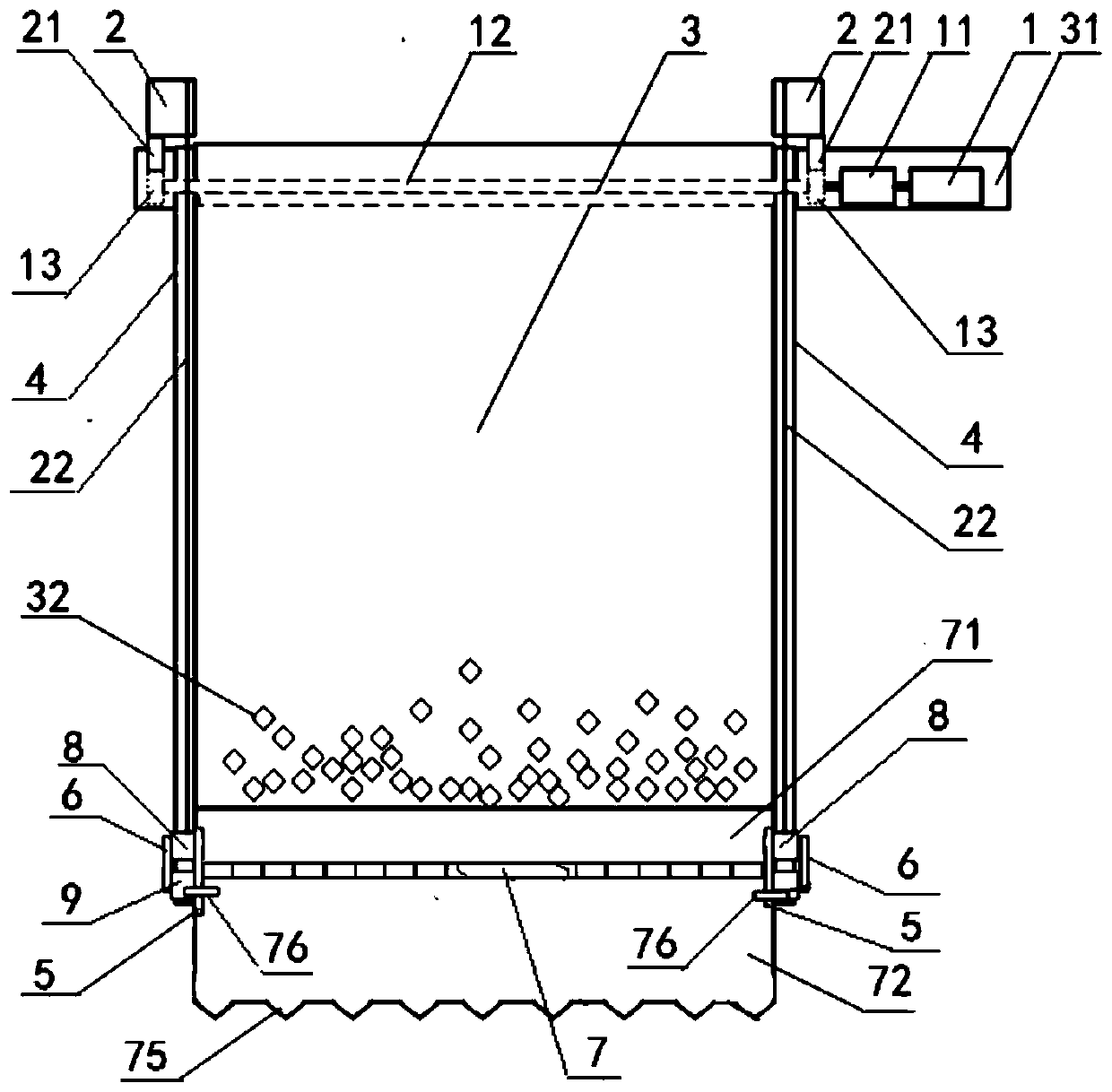
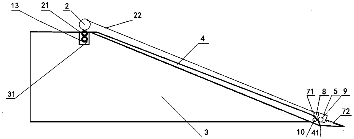
[0051] see Figure 1 to Figure 11, a kind of flattening device for car test ramp gravel shown, comprises the traction mechanism that is located at the two ends of the transverse groove 31 of test ramp 3 top, is located at the track 4 on the test ramp 3 and is located at the track 4 On the flat scraper trolley, the lower end of the track 4 is provided with a downward curved section 41, which is bent into a downward curved section at the lower end of the track. When the scraper descends to the lower end of the track, there is a larger drop rate, so that the scraper and the road adjacent to the test ramp form a small slope, which is convenient for the test vehicle to drive into the test ramp. Its salient substantive features are:
[0052] The traction mechanism includes a driving motor 1 arranged in one end of the transverse groove 31, a speed reducer 11 matingly connec...
PUM
 Abstract
Description
Claims
Application Information
PatSnap Eureka turns technology decisions into work you can execute. Powered by our Innovation Knowledge Graph, it runs expert workflows across engineering, life sciences, materials and intellectual property. Get your review-ready output in minutes.


