A fast self-test method for fiber optic gyroscope startup

A fiber optic gyroscope and self-inspection technology, which is applied to Sagnac effect gyroscopes, measuring devices, instruments, etc., can solve problems such as inability to guarantee the normal operation of the fiber optic gyroscope, unfavorable control of the size of the circuit board, and abnormal operation of the fiber optic gyroscope. The effect of reliable detection results, fast detection speed, and no increase in complexity

Active Publication Date: 2021-08-10
HENGYANG TRANSISTOR
View PDF5 Cites 0 Cited by
  • Summary
  • Abstract
  • Description
  • Claims
  • Application Information

AI Technical Summary

Problems solved by technology

This is very unfavorable for the size control of the circuit board itself
[0007] In addition, the increased circuit part for detecting optical power has its own reliability problems. When the increased electronic components work abnormally, the detection information will be misreported and falsely reported, which will affect the normal use of optical fibers.
The more important problem is that the optical power reaching the detector is only a part of the loop gain, and the failure of the detection circuit will also cause the abnormal operation of the fiber optic gyroscope, but the detection of the detection optical power cannot guarantee the normal operation of the overall loop of the fiber optic gyroscope

Method used


Image

  • A fast self-test method for fiber optic gyroscope startup
  • A fast self-test method for fiber optic gyroscope startup
  • A fast self-test method for fiber optic gyroscope startup

Examples


Embodiment Construction

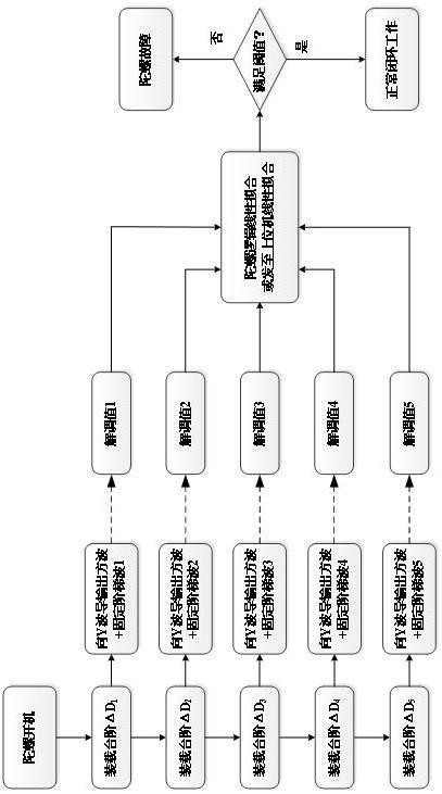
[0033] The present invention will be described in further detail below in conjunction with accompanying drawing of description:

[0034] Such as image 3 As shown, in order to ensure the accuracy of the loop gain test, the step height of the ladder wave is selected as 5 types, and at the same time, it can ensure the high-speed detection without affecting the normal work after the power-on detection. After the fiber optic gyroscope is powered on, it sends The step height is , , , , At the same time, the modulated square wave is sent to the Y waveguide. In order to minimize the influence of the ladder wave on the follow-up work of the fiber optic gyroscope, the height of the steps sent should be reduced in turn. An applicable combination of the step height of the ladder wave is: 10bits , 8bits, 6bits, 4bits, 2bits, but it needs to be adjusted according to different types of fiber optic gyroscopes. The above combination of step heights can be basically satisfied, the ph...


PUM


Abstract

A fast self-detection method for fiber optic gyroscope startup, which is characterized in that the corresponding demodulation value is linearly fitted to obtain the loop gain value, and the loop gain value obtained by the test fitting is compared with the preset threshold value to determine the fiber optic gyroscope. Gyro loop status. The self-checking problem of the fiber optic gyroscope is solved by software method, and the modulation and demodulation characteristics of the fiber optic gyroscope are fully utilized. The method is simple to implement, does not increase the complexity of the fiber optic gyroscope software, and does not affect the normal operation of the fiber optic gyroscope after startup. The detection speed is fast, and the time required is less, and the time to give the required detection information and results is generally less than 1ms. The detection results can be realized flexibly. The detection results can be given inside the fiber optic gyroscope software, and can also be processed by the host computer to obtain the results. The detection information is more comprehensive and the detection results are more reliable. The information given includes the overall loop of the fiber optic gyroscope, and any fault in the loop can be reflected in the test results.

Description

technical field [0001] The invention relates to the field of self-testing of equipment, in particular to a fast self-testing method for fiber optic gyroscope startup. Background technique [0002] Fiber optic gyroscope is an angular velocity sensor based on the Sagnac effect. The rotation causes a phase difference between the two oppositely propagating beams of light in the sensitive ring, which is proportional to the rotational speed. The two beams of light will interfere at the output end, and the corresponding rotational speed can be demodulated by detecting the change of light intensity. Due to the good reciprocity structure of the fiber optic gyroscope itself, with the increasing maturity of the device and technology level, the fiber optic gyroscope has achieved very superior performance at present. Due to the advantages of no dynamic parts, high reliability, large measurement range, shock resistance, small size, light weight, low cost, and suitable for mass productio...

Claims


Application Information

Patent Timeline
Patent Type & Authority Patents(China)
IPC IPC(8): G01C19/72G01C25/00
Inventor 高爽李爱夫李柯烨卢佳振
Owner HENGYANG TRANSISTOR
Why Eureka
Try Eureka