Wind driven generator

A technology for wind turbines and ventilation pipes, which is applied to the static parts of the magnetic circuit, the shape/style/structure of the magnetic circuit, etc., which can solve the problems of difficulty in improving the cooling efficiency and the limited effective heat dissipation area of ​​the stator, and achieve the improvement of cooling effect and increase Large effective heat dissipation area and low electromagnetic influence

Active Publication Date: 2019-06-25
ZHEJIANG UNIV +1
View PDF10 Cites 4 Cited by
  • Summary
  • Abstract
  • Description
  • Claims
  • Application Information

AI Technical Summary

Problems solved by technology

[0004] The technical problem to be solved by the present invention is to provide a wind power generator in order to overcome the defects

Method used


Image

  • Wind driven generator
  • Wind driven generator
  • Wind driven generator

Examples


Embodiment 1

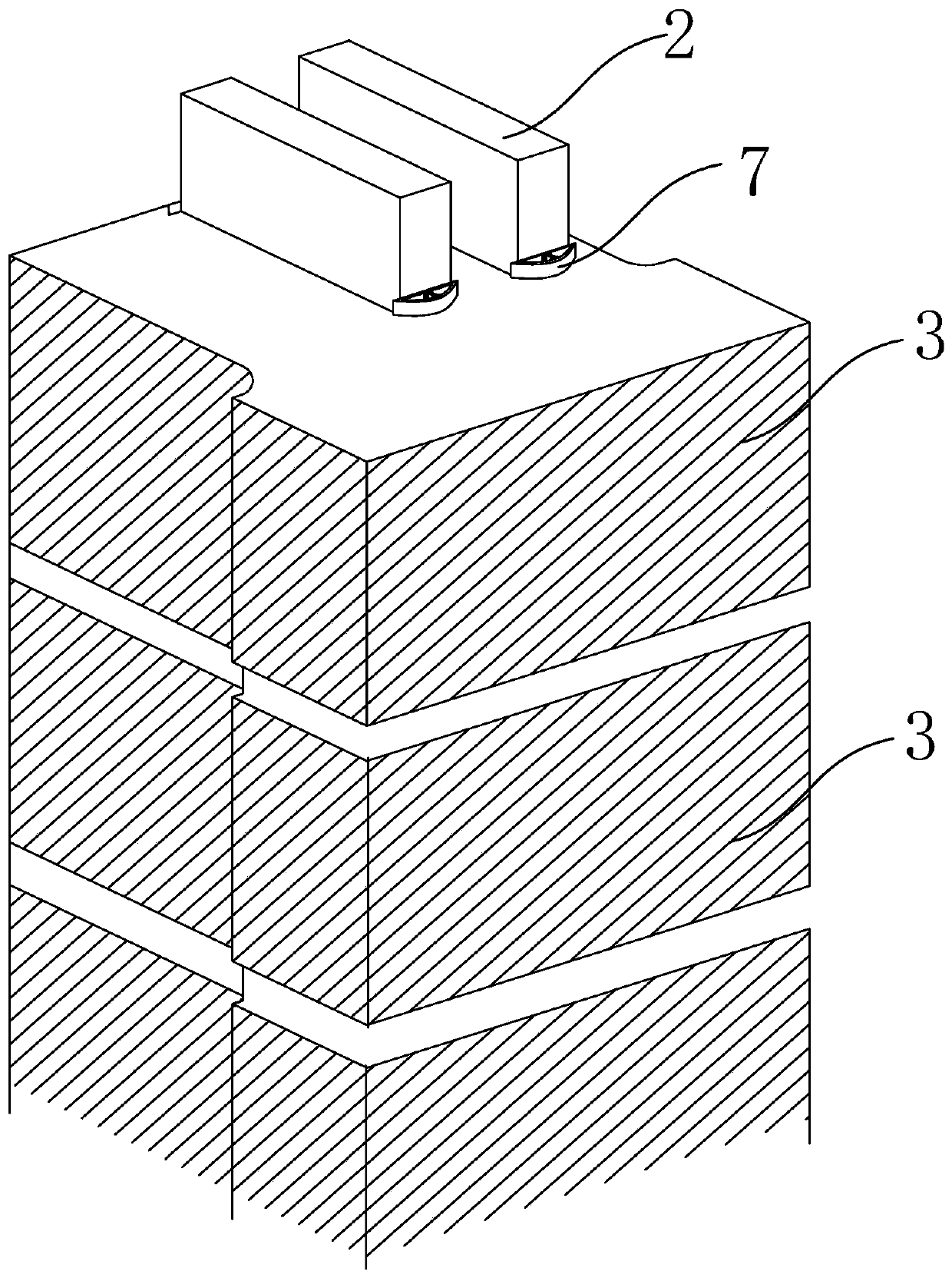
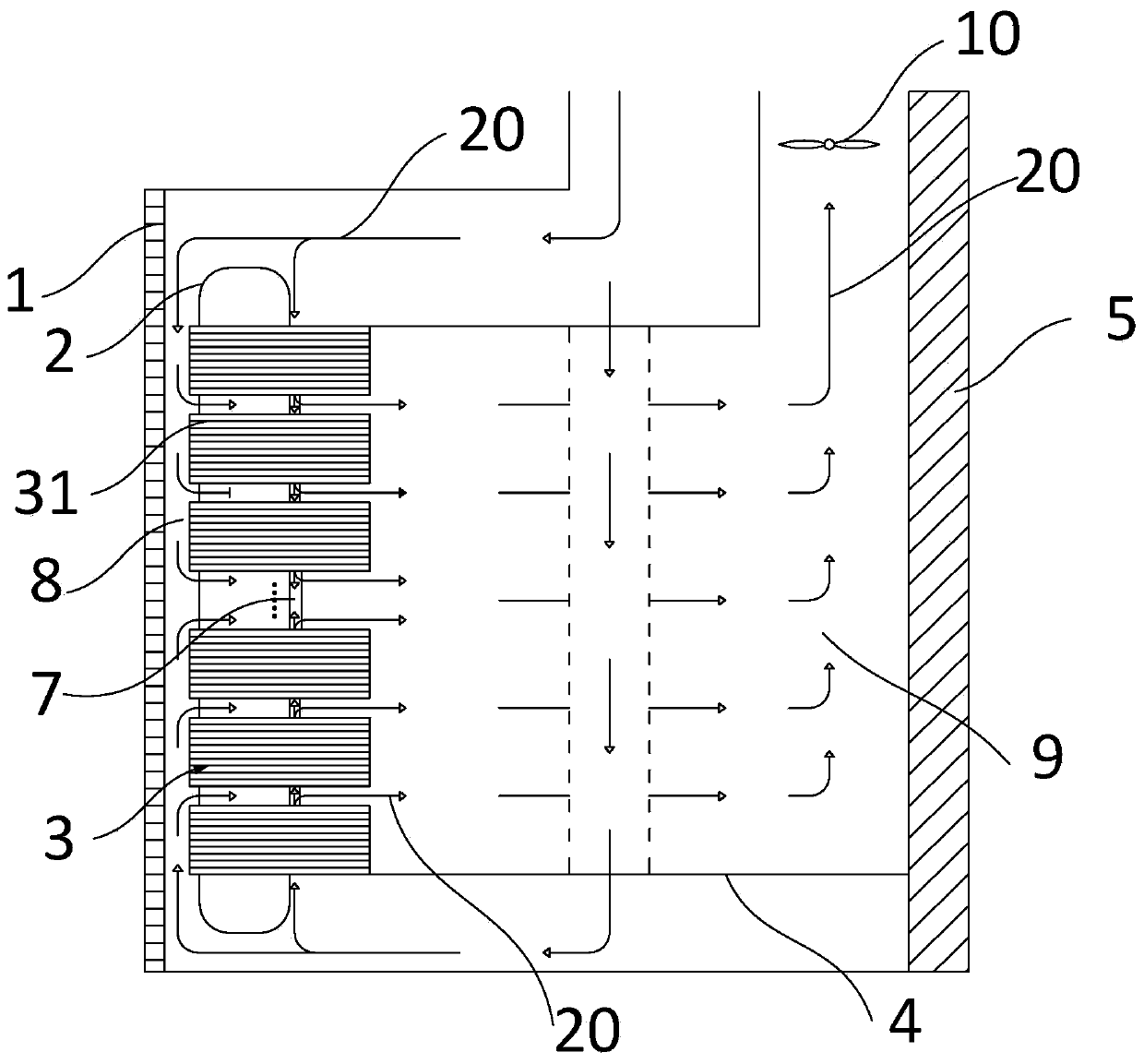
[0047] Such as Figure 1 to Figure 3 As shown, the present invention provides a wind generator, which includes a rotor 1, a stator and an air gap 8 between the rotor 1 and the stator, the stator includes a stator coil 2 and a stator core 3, and the radial inner side of the stator core 3 , The internal space enclosed by the stator central part 5 and the stator end plate 4 forms a cavity 9 . The stator core 3 has a tooth slot structure, and the stator coil 2 is located in the slot of the stator core 3 . The stator core 3 includes a number of laminations 31 with gaps between them. The laminations 31 are formed by stacking a plurality of silicon steel sheets with cogged structures along the axial direction of the wind turbine. The two ends of the stator core 3 It is compressed and fixed by the stator end plate 4 along the axial direction of the generator. The space between each lamination group 31 forms a radial ventilation channel of the stator, and the radial ventilation chann...

Embodiment 2

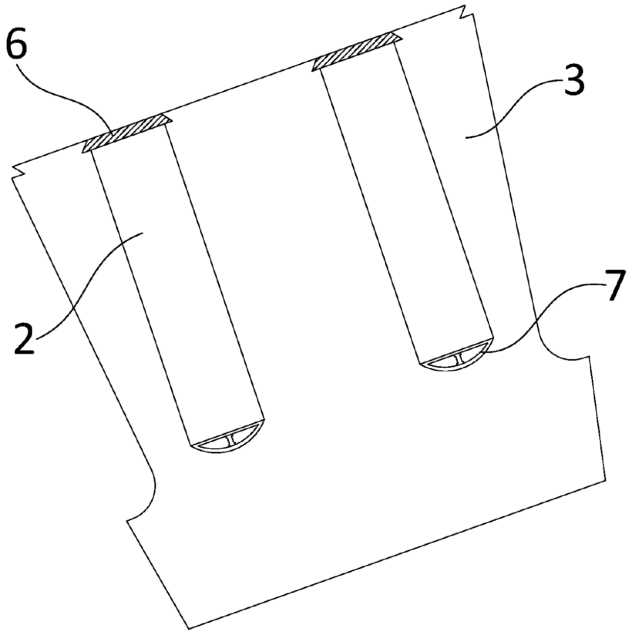
[0057] Such as Figure 6 As shown, the structure of this embodiment is basically the same as that of Embodiment 1, the difference is that the ventilation pipe 7 is composed of several ventilation components 72 . Both ends of the ventilation assembly 72 are movably connected to each other to form an integral ventilation pipe 7 . One end of the two ventilation components 72 located at the two ends of the installation groove is respectively provided with an axial fixing structure for preventing the displacement of the ventilation pipe 7 in the axial direction of the stator.

[0058] One end of the ventilation component 72 is provided with at least one protrusion, and the other end is provided with a connection groove corresponding to the protrusion, and the ventilation components 72 are connected to each other through the protrusion and the connection groove. In other embodiments, two adjacent ventilation components 72 may also be connected by bonding or other flexible connectio...


PUM

PropertyMeasurementUnit
Radianaaaaaaaaaa

Abstract

The invention provides a wind driven generator, and the wind driven generator comprises a rotor, a stator and an air gap located between the rotor and the stator. The stator comprises a stator coil and a stator core. The radial inner side of the stator iron core, a central part of the stator and an inner space formed by the enclosing of an end plate of the stator forms a cavity. The stator core isof a tooth slot structure, and the stator coil is located in a stator core trench. The wind driven generator further comprises a generator cooling device, and the generator cooling device comprises aventilation pipe, wherein the ventilation pipe is located between the stator iron core and the stator coil and adjacent to the stator coil and the stator iron core. According to the wind driven generator, the ventilation pipe is arranged at the bottom of the stator core trench and makes contact with the stator coil, thereby increasing the effective heat dissipation area of the stator, and reducing the pressure loss of gas flowing in the generator; compared with a traditional cooling mode, the generator improves the cooling effect, and the design that the ventilation pipe is located at the bottom of the stator core trench has low electromagnetic influence on the stator.

Description

technical field [0001] The invention relates to the field of wind power generation, in particular to a wind power generator. Background technique [0002] During the operation of the wind turbine generator, the loss due to operation will increase the temperature inside the generator, and when the temperature of some components in the generator is too high, it will cause damage to a certain extent, in severe cases Even affect the normal operation of the generator. Therefore, the temperature rise of these components must be effectively controlled to ensure the stable and normal operation of the generator. Most of the loss occurs in the stator coil winding, which makes the temperature rise of the stator coil and the components connected to it much higher than other components. Excessive coil temperature will accelerate the aging of winding insulation, and even cause winding insulation failure. Therefore, how to cool the generator stator coil reasonably and effectively is one...

Claims


Application Information

Patent Timeline
IPC IPC(8): H02K1/20
Inventor 吴立建闻汇施杨王海洋刘军伟方攸同
Owner ZHEJIANG UNIV
Why Eureka
Try Eureka