Supercharge Your Innovation With Domain-Expert AI Agents!

Control circuit and flyback converter applying same

A technology of flyback converter and control circuit, which is applied in the direction of adjusting electrical variables, control/regulation system, output power conversion device, etc., can solve the problems of power consumption increase, output voltage ripple, voltage ripple, etc., and achieve Reduce energy, reduce output voltage ripple, and improve system efficiency

Active Publication Date: 2019-06-25
SILERGY SEMICON TECH (HANGZHOU) CO LTD
View PDF1 Cites 2 Cited by
  • Summary
  • Abstract
  • Description
  • Claims
  • Application Information

AI Technical Summary

Problems solved by technology

[0004] To sum up, on the one hand, the energy transmitted by the constant on-time control method may be greater than the output energy at light load, resulting in increased power consumption and reduced light-load efficiency; on the other hand, in intermittent operation, the power stage circuit During the stop working period, the output energy is provided by the output capacitor (usually an electrolytic capacitor), and there is a large voltage ripple on the output capacitor, resulting in a large ripple in the output voltage, which in turn affects the working performance of the circuit system

Method used


Image

  • Control circuit and flyback converter applying same
  • Control circuit and flyback converter applying same
  • Control circuit and flyback converter applying same

Examples


Embodiment Construction

[0040] The present invention is described below based on examples, but the present invention is not limited to these examples. In the following detailed description of the invention, some specific details are set forth in detail. The present invention can be fully understood by those skilled in the art without the description of these detailed parts. In order not to obscure the essence of the present invention, well-known methods, procedures, procedures, components and circuits have not been described in detail.

[0041] Additionally, those of ordinary skill in the art will appreciate that the drawings provided herein are for illustrative purposes and are not necessarily drawn to scale.

[0042] Meanwhile, it should be understood that in the following description, "circuit" refers to a conductive loop formed by at least one element or sub-circuit through electrical connection or electromagnetic connection. When an element or circuit is said to be "connected to" another eleme...


PUM


Abstract

The invention discloses a control circuit. According to the technical scheme of the embodiment of the invention, a voltage compensation signal is divided into different ranges during a light load; andthe switching frequency and the conduction time of a power switch of a flyback converter are adjusted in a segmented manner according to the voltage compensation signal, so that a power-level circuitworks continuously, the transmitted energy is reduced, the output voltage ripples are effectively reduced, and the system efficiency is improved.

Description

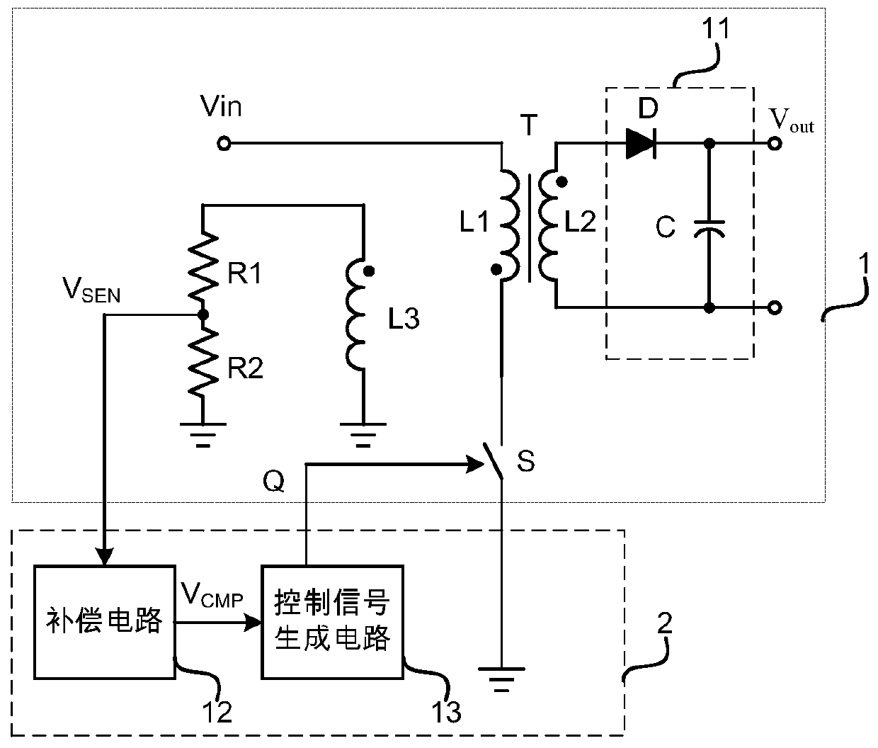
technical field [0001] The invention relates to power electronic technology, in particular to a control circuit and a flyback converter using the same. Background technique [0002] When the load is light, the conversion efficiency of the flyback converter will be very low. Therefore, in order to improve the efficiency, in the design of the flyback converter, the control method at light load is generally treated specially. [0003] In the prior art, generally when the load is light, the flyback converter usually adopts a constant on-time control mode and an intermittent operation mode to reduce the energy transmitted by the power stage circuit. In the constant on-time control mode, the on-time of the switch control signal at each switching frequency remains constant, and the on-time is set by the user according to the application environment, while changing the switching frequency (off-time change) to provide required output power. However, under some light load condition...

Claims


Application Information

Patent Timeline
IPC IPC(8): H02M3/335H02M1/08H02M1/14
Inventor 赖洪斌
Owner SILERGY SEMICON TECH (HANGZHOU) CO LTD
Features
  • R&D
  • Intellectual Property
  • Life Sciences
  • Materials
  • Tech Scout
  • Unparalleled Data Quality
  • Higher Quality Content
  • 60% Fewer Hallucinations
Learn More