Bottle cap double-sided laser marking equipment

A technology of marking equipment and bottle caps, which is applied in welding equipment, laser welding equipment, metal processing equipment, etc., can solve the problems of reduced coding quality and achieve the effect of improving quality

Active Publication Date: 2019-06-28
德玛克(浙江)精工科技有限公司
View PDF11 Cites 2 Cited by
  • Summary
  • Abstract
  • Description
  • Claims
  • Application Information

AI Technical Summary

Problems solved by technology

[0006] The present invention provides a double-sided laser marking equipment for bottle caps in view of the deficiencies of the prior art. By setting up a bottle cap arrangement device, the bottle caps in the bottle cap arrangement device are transferred to the bottle caps with the front face up and the reverse side is transferred to the bottle cap arrangement. After being rearranged by the bottle cap arrangement device, the bottle caps in the device are transported to the height compensation device in the form of front and back sides at intervals. After the height compensation, the front and back sides are coded in the coding area, and the automatic height compensation makes up for the height difference between the first side coding and the second side coding, which greatly improves the quality of bottle cap coding , which solves the technical problem that the coding quality is greatly reduced when the second side is coded due to the height difference in the prior art

Method used


Image

  • Bottle cap double-sided laser marking equipment
  • Bottle cap double-sided laser marking equipment
  • Bottle cap double-sided laser marking equipment

Examples


Embodiment 1

[0063] The following describes in detail the embodiments of the present invention, examples of which are illustrated in the accompanying drawings, wherein the same or similar reference numerals refer to the same or similar elements or elements having the same or similar functions throughout. The embodiments described below with reference to the accompanying drawings are exemplary, and are intended to explain the present invention and should not be construed as limiting the present invention.

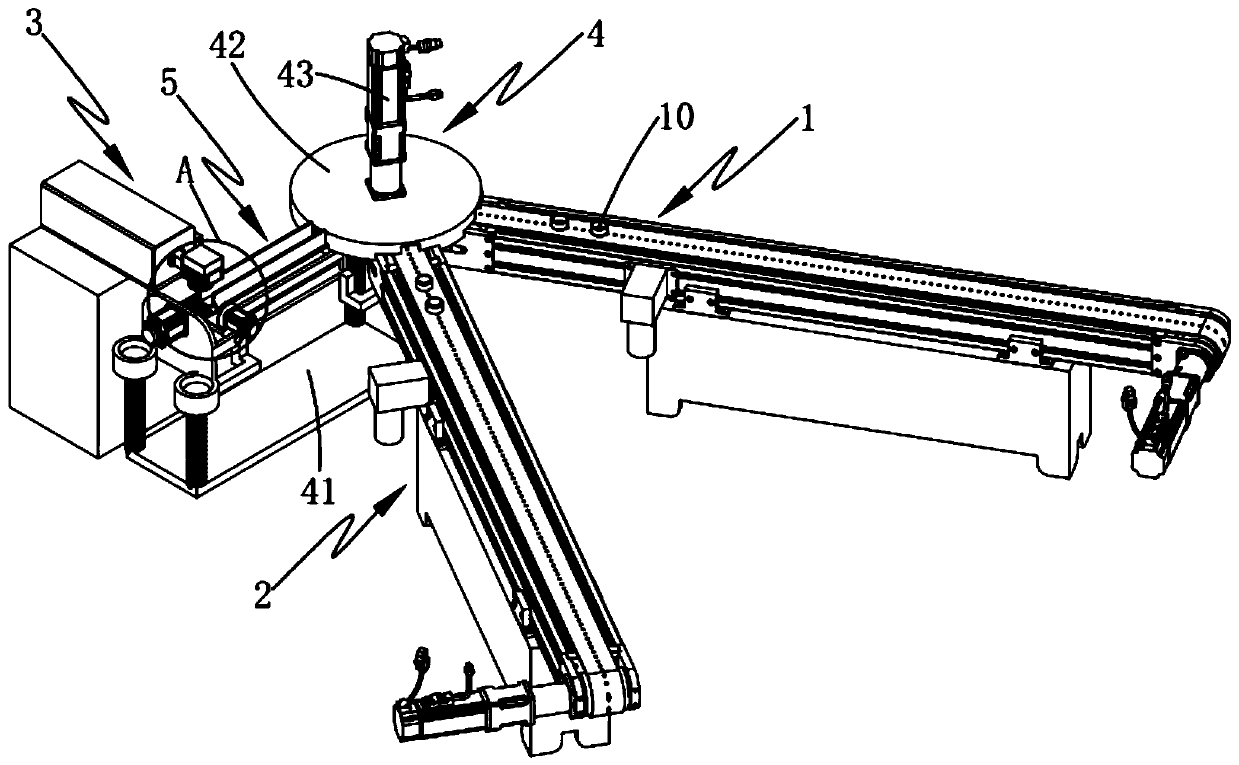
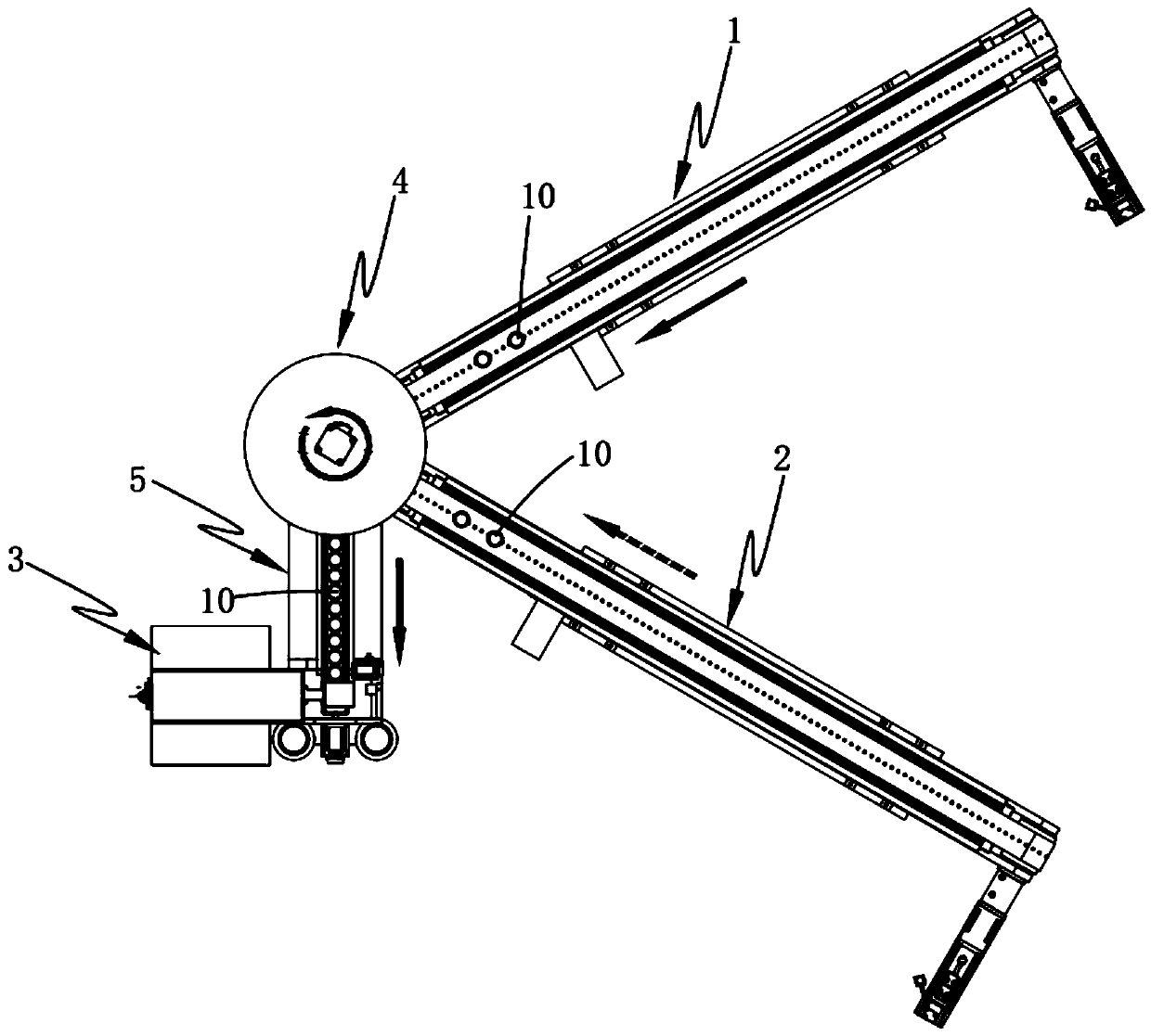
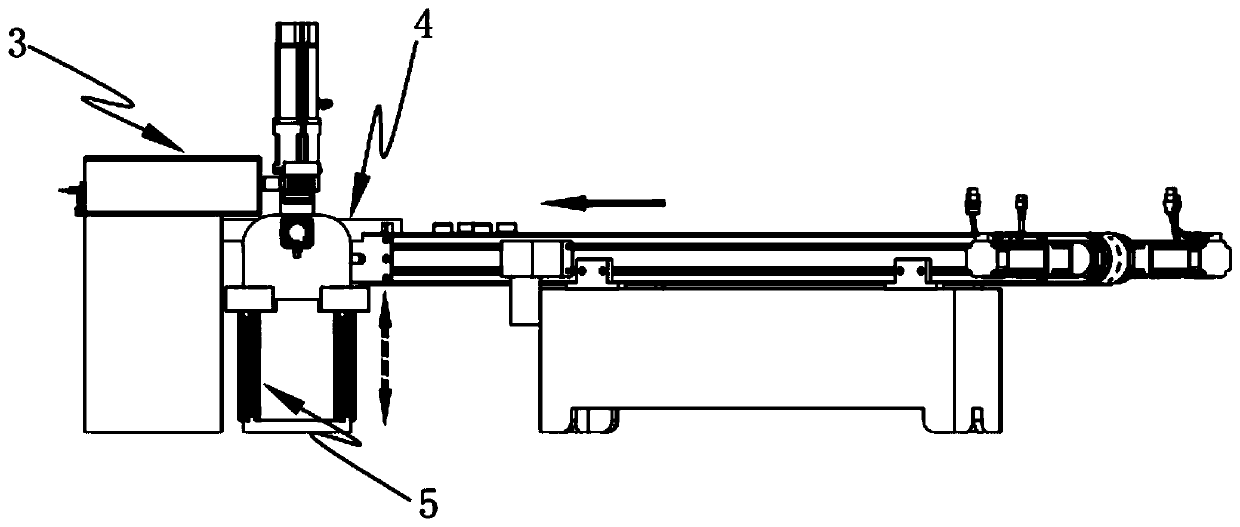
[0064] like figure 1 , 2 As shown in and 3, a double-sided laser marking equipment for bottle caps includes a front feeding device 1, a reverse feeding device 2 and a laser coding device 3, and also includes:

[0065] Bottle cap arranging device 4, the bottle cap arranging device 4 is arranged on one side of the front feeding device 1 and the reverse feeding device 2, and the bottle cap arranging device 4 is respectively connected with the front feeding device 1 and the reverse side. T...


PUM


Abstract

The invention provides bottle cap double-sided laser marking equipment. The bottle cap double-sided laser marking equipment comprises a front feeding device, a back feeding device, a laser code printing device, a bottle cap arranging device and a height compensating device. The bottle cap arranging device is arranged on one sides of the front feeding device and back feeding device. The height compensating device is arranged on one side of the output end of the bottle cap arranging device, and the laser coding device is arranged at the output end of the height compensating device. A code printing area is formed between the height compensating device and the laser code printing device. The bottle cap arranging device is arranged, so that bottle caps can be conveyed into the height compensating device in the manner that the bottle caps are arranged at intervals on the front and back sides. Meanwhile, when the bottle cap arranging device is used for arranging the bottle caps, the height compensating device is synchronously driven to carry out height compensation in the bottle cap turnover process, front and back code printing processing is carried out in the code printing area, and automatic height compensation is carried out. The technical problem that in the prior art, due to height differences, the code printing quality is greatly reduced during code printing of a second surfaceis solved.

Description

technical field [0001] The invention relates to the technical field of bottle cap processing, in particular to a double-sided laser marking device for bottle caps. Background technique [0002] In the current beverage market, digital codes, character codes or simple patterns are generally printed on beverage bottle caps for anti-counterfeiting and promotion, and the actual operability is relatively poor, and the establishment of a traceability system cannot be realized. At present, the technology of similar equipment adopts ink jet coding, printing, labeling, bronzing and other processes to realize the process of marking or printing on the outer or inner surface of beverage bottle caps. [0003] Inkjet printed patterns and QR codes cannot be in direct contact with food and are easy to fall off. Printing also has the problem of ink pollution, and the two-dimensional code cannot achieve dynamic variable printing, that is, it cannot achieve one cover and one code. Labeling is...

Claims


Application Information

Patent Timeline
IPC IPC(8): B23K26/362B23K26/70
CPCB41J2/442B41J3/407
Inventor 王巍植
Owner 德玛克(浙江)精工科技有限公司
Why Eureka
Try Eureka