Positioning clamp

A positioning fixture and front positioning technology, which is applied in the direction of positioning devices, clamping, manufacturing tools, etc., can solve the problems of increasing the overall size of the worktable, occupying a large space, and low applicability, so as to reduce the processing preparation time and improve efficiency. , great applicability

Pending Publication Date: 2019-06-28
宇晶机器(长沙)有限公司
View PDF0 Cites 4 Cited by
  • Summary
  • Abstract
  • Description
  • Claims
  • Application Information

AI Technical Summary

Problems solved by technology

These consumer-type plate glass parts usually use multi-spindle, multi-station for automatic high-efficiency processing to achieve mass production, and the positioning and clamping must be carried out before the workpiece blank is processed by the CNC machine tool to ensure the smooth progress of the processing At present, it is generally used in the industry to perform unilateral positioning through a group of V-shaped blocks. This positioning method causes the panel to not be in the center position on the adsorption table, forming a situation where one side is more and the other side is less, and the V-shaped positioning requires Adjusting the length of the positioning block according to the length of the panel has low applicability; at the same time, a set of positioning device can only locate one workpiece blank. With the increase of processing stations, the same number of positioning devices needs to be installed, which consumes a lot of cost and occupies A lot of space; and usually the positioning device is installed on the worktable, and the overall size of the worktable needs to be increased as the number of workstations increases

Method used


Image

  • Positioning clamp
  • Positioning clamp
  • Positioning clamp

Examples


Embodiment Construction

[0025] The present invention will be further described below in conjunction with the accompanying drawings and embodiments.

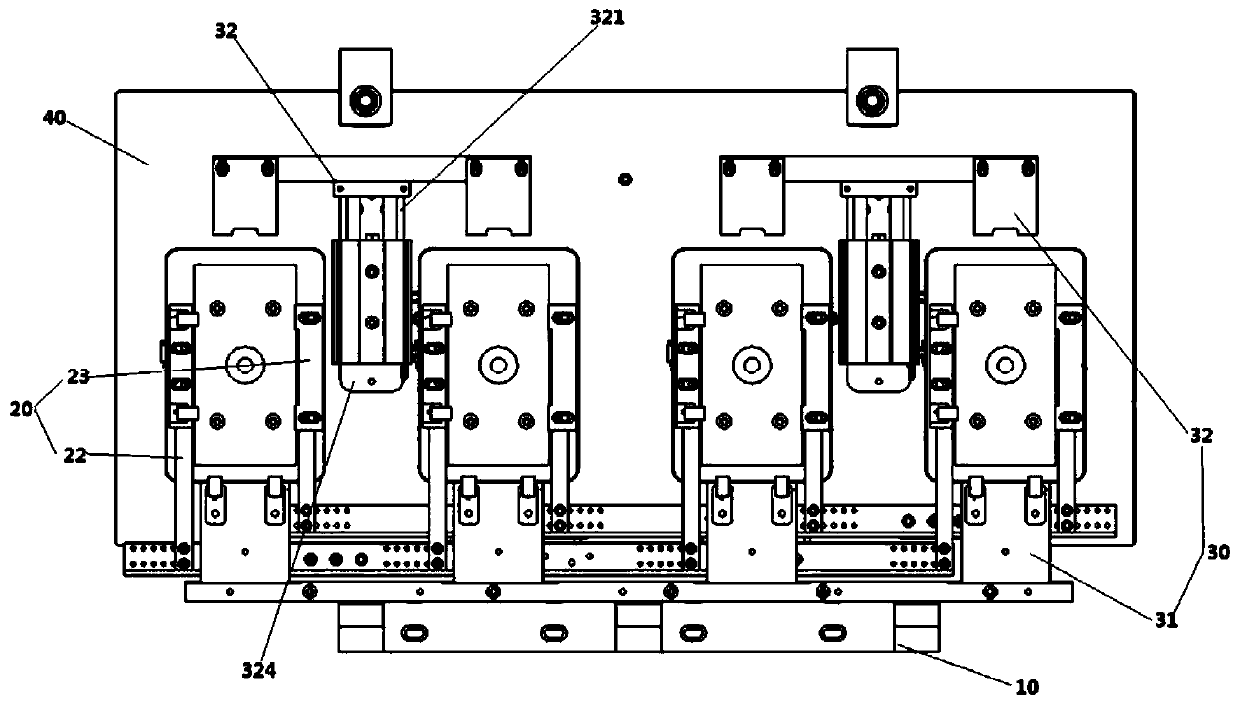
[0026] refer to figure 1 , the present embodiment includes a bracket 10, a left and right positioning mechanism 20, a front and rear positioning mechanism 30 and a working surface 40;

[0027] The support 10 includes a base mounting plate 11, the base mounting plate 11 can be installed on the machine tool, a plurality of support plates 12 are installed on the base mounting plate 11, and the support plates 12 support the left and right positioning mechanisms 20;

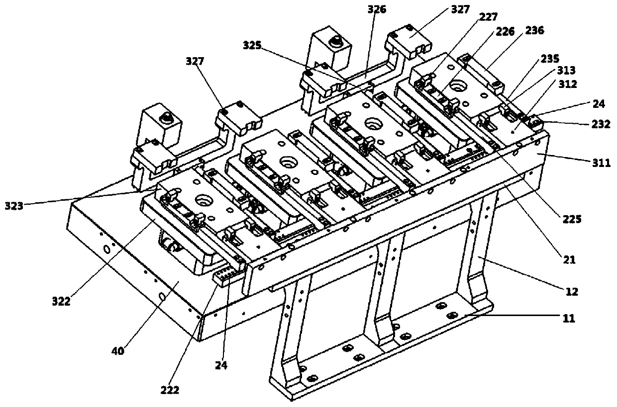
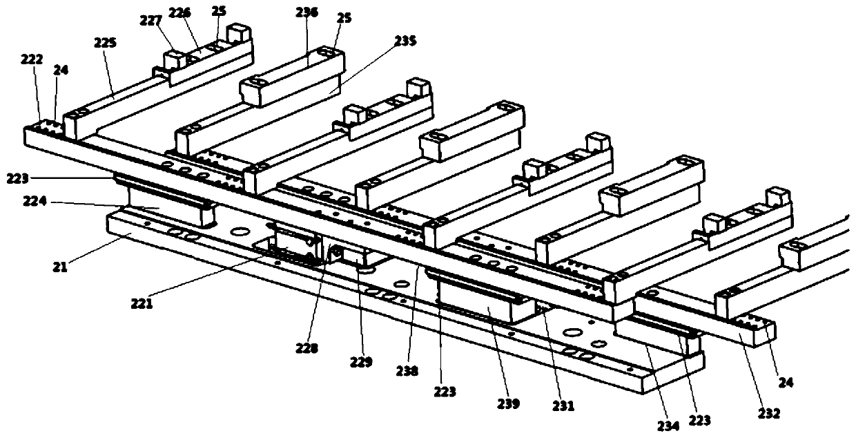
[0028] The left and right positioning mechanism 20 includes a left and right mounting base plate 21, a left positioning mechanism 22 and a right positioning mechanism 23;

[0029] Described left positioning mechanism 22 comprises driving cylinder one 221, cylinder connection block one 228, cylinder fixed block one 229, left positioning base 222, sliding line rail 223, line rail mounting seat o...


PUM


Abstract

The invention provides a positioning clamp. The positioning clamp comprises a support, a left-and-right positioning mechanism, a front-and-back positioning mechanism and a worktable board, wherein thesupport supports the left-and-right positioning mechanism, the left-and-right positioning mechanism comprise a left-and-right installing bottom plate, a left positioning mechanism and a right positioning mechanism, wherein the left positioning mechanism comprises a driving air cylinder I, an air cylinder connecting block I, an air cylinder fixing block I, a left positioning base, a sliding wire rail, a line rail installing base I, a left torsion spring base, a torsion spring installing base and a torsion spring positioning block; the right positioning mechanism comprises a driving air cylinder II, an air cylinder connecting block II, an air cylinder fixing block II, a right positioning base, a sliding wire rail, a line rail installing base II, a right base and a right positioning block; the front-and-right positioning mechanism comprises a front positioning mechanism and a back positioning mechanism, wherein the front positioning mechanism comprises a front positioning base, a front installing base and a front positioning block; and the back positioning mechanism comprises a bottom plate cushion block, an adsorbing table base, an adsorbing table, an air cylinder installing base, adriving air cylinder III, an installing base and a back positioning block. According to the clamp, centring can be achieved, a plurality of workpieces can be positioned at the same time and the clampdoes not greatly occupy the worktable board.

Description

technical field [0001] The invention relates to the technical field of machine tool processing, in particular to a positioning fixture. Background technique [0002] In the prior art, machine tools are usually used to fine-process workpiece blanks to form shaped workpieces. The workpiece blanks have various shapes, such as blocks, plates, and even irregular bodies. [0003] In the glass industry, the shape and size of glass products span a large range, but the processing methods are basically the same. These consumer-type plate glass parts usually use multi-spindle, multi-station for automatic high-efficiency processing to achieve mass production, and the positioning and clamping must be carried out before the workpiece blank is processed by the CNC machine tool to ensure the smooth progress of the processing At present, it is generally used in the industry to perform unilateral positioning through a group of V-shaped blocks. This positioning method causes the panel to not ...

Claims


Application Information

Patent Timeline
Patent Type & Authority Applications(China)
IPC IPC(8): B23Q3/08B23Q3/18
Inventor 杨佳葳王珲荣晁阳升
Owner 宇晶机器(长沙)有限公司
Why Eureka
Try Eureka