
MOS tube supplying mechanism for power amplification component

A technology of MOS tube and power amplifier components, which is applied in the field of MOS tube supply mechanism, can solve the problems of inconvenient material bar transposition, unfavorable production continuity, inconvenient material bar feeding stability, etc., so as to facilitate material replacement and reclaiming. , to ensure the effect of stable production

Active Publication Date: 2019-06-28
安徽源芯微电子有限责任公司
View PDF6 Cites 2 Cited by
  • Summary
  • Abstract
  • Description
  • Claims
  • Application Information

AI Technical Summary

Problems solved by technology

[0008] The purpose of the present invention is to provide a MOS tube supply mechanism for a power amplifier assembly, to solve the current inconvenient to ensure the stability of feeding the material strips, inconvenient to observe the situation of feeding the material strips, and inconvenient to quickly adjust the The transposition of the material strips is not convenient for the rapid unloading of the front side material strips, it is not conducive to ensuring the continuity of production, it is not convenient to ensure the interval stability of the MOS tubes on the conveyor belt, and it is not conducive to the stable and continuous feeding of the MOS tube feeding mechanism question

Method used


Image

  • MOS tube supplying mechanism for power amplification component
  • MOS tube supplying mechanism for power amplification component
  • MOS tube supplying mechanism for power amplification component

Examples


Embodiment Construction

[0034] The following will clearly and completely describe the technical solutions in the embodiments of the present invention with reference to the accompanying drawings in the embodiments of the present invention. Obviously, the described embodiments are only some, not all, embodiments of the present invention. Based on the embodiments of the present invention, all other embodiments obtained by persons of ordinary skill in the art without making creative efforts belong to the protection scope of the present invention.

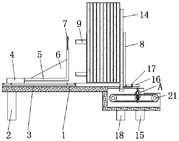
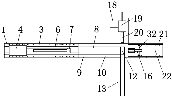
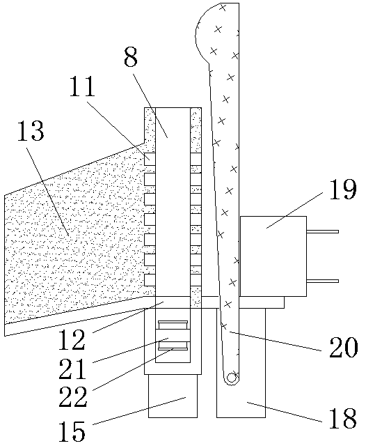
[0035] see Figure 1-8 , the present invention provides a technical solution: a MOS tube supply mechanism for a power amplifier assembly, including a platen 1, a first bracket 2, an electric push slide rail 3, an electric push slide table 4, a push plate 5, a stabilizing plate 6, an adjustment Mechanism 7, limit plate 8, extension plate 9, side plate 10, drain 11, discharge port 12, guide groove 13, material strip 14, second bracket 15, thumb cylinder 16, moun...


PUM


Abstract

The invention discloses an MOS tube supplying mechanism for a power amplification component. The MOS tube supplying mechanism comprises a bedplate and a first shaft rod, wherein the left side of the bottom end of the bedplate is fixedly provided with a first support, the upper portion of a pushing plate is provided with a stabilizing plate, an adjusting mechanism comprises an adjusting plate, an adjusting rod and stabilizing rods, the MOS tube supplying mechanism further comprises a position-limiting plate, the front and rear two sides of the position-limiting plate are both fixedly provided with side plates in a welded manner, material strips are placed inside the position-limiting plate, the MOS tube supplying mechanism further comprises a second support, the second support is fixed to the lower portion of the right side of the bedplate, the inner surface of a conveyor belt is fixedly provided with a toothed bar, and the middle portion of the inner side of the conveyor belt is provided with a second shaft rod. By means of the MOS tube supplying mechanism for the power amplification component, the material strip feeding stability is conveniently guaranteed, the material strip feeding situation is conveniently observed, position changing is conveniently and rapidly performed on the material strips, rapid unloading of the front-side material strips is facilitated, the interval stability of MOS tubes on the conveyor belt is conveniently guaranteed, stable and continuous material fetching of an MOS tube feeding mechanism is facilitated, and rapid production is facilitated.

Description

technical field [0001] The invention relates to the related technical field of power amplifier components, in particular to a MOS tube supply mechanism of the power amplifier component. Background technique [0002] The power amplifier component can amplify the sound frequency and is indispensable in various power amplifier equipment. Among them, the MOS tube is an important component in the power amplifier component. When the power amplifier component is produced, it needs to supply the MOS tube. In order to ensure the rapid production and installation of power amplifier components; [0003] Although with the development of existing technology, the existing MOS tube supply mechanism of power amplifier components has made great improvements, but the existing MOS tube supply mechanism still has certain disadvantages: [0004] 1. It is inconvenient to ensure the stability of feeding strips, and it is not convenient to observe the feeding situation of strips; [0005] 2. It i...

Claims


Application Information

Patent Timeline
IPC IPC(8): B65G47/28B65G47/08
Inventor 欧召辉张荔朱巧艳
Owner 安徽源芯微电子有限责任公司
Learn More