Integrated circuit material grabbing and putting device

An integrated circuit and material technology, applied in the direction of conveyor objects, transportation and packaging, conveyors, etc., can solve the problems of complex equipment structure, low operation efficiency, and low efficiency of grabbing units

Active Publication Date: 2019-06-28
深圳格芯集成电路装备有限公司
View PDF5 Cites 6 Cited by
  • Summary
  • Abstract
  • Description
  • Claims
  • Application Information

AI Technical Summary

Problems solved by technology

[0003] During the production and processing of various small regular materials, a lot of work is required for pick-and-place handling. Currently, the gripper devices used more often can only grab one at a time, and some can grab multiple objects at a time, but they cannot be adjusted. spacing between objects
At present, the requirements for UPH (units per hour) value in the field of integrated circuit testing are constantly being refreshed. The efficiency of traditional manual operations is too low, and the general single gripper is far from meeting the needs of use. Therefore, multi-gripper equipment is used. However, in the process of testing, packaging, marking, etc., the chips must be directly circulated on different trays and workstations. The spacing between different trays and chips during work is different. Each of the existing multi-handle equipment Each grabbing unit is independently controlled and adjusted separately. The corresponding equipment structure is complex and bulky. The efficiency of each grabbing unit is low when adjusting the relative distance, and the adjustment accuracy is not high, which reduces the material flow speed and production efficiency.

Method used


Image

  • Integrated circuit material grabbing and putting device
  • Integrated circuit material grabbing and putting device
  • Integrated circuit material grabbing and putting device

Examples


Embodiment Construction

[0040] The specific implementation manners of the present invention will be further described in detail below in conjunction with the accompanying drawings and embodiments. The following examples are used to illustrate the present invention, but are not intended to limit the scope of the present invention.

[0041] In the description of the present invention, it should be understood that the orientation or positional relationship indicated by the terms "upper", "lower", "left", "right", "top", "bottom" etc. Orientation or positional relationship is only for the convenience of describing the present invention and simplifying the description, and does not indicate or imply that the referred device or element must have a specific orientation, be constructed and operated in a specific orientation, and thus should not be construed as a limitation of the present invention.

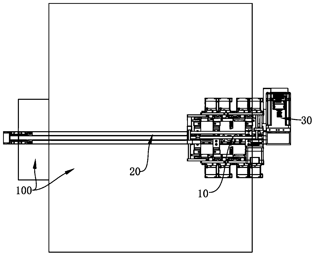
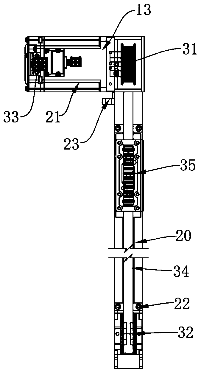
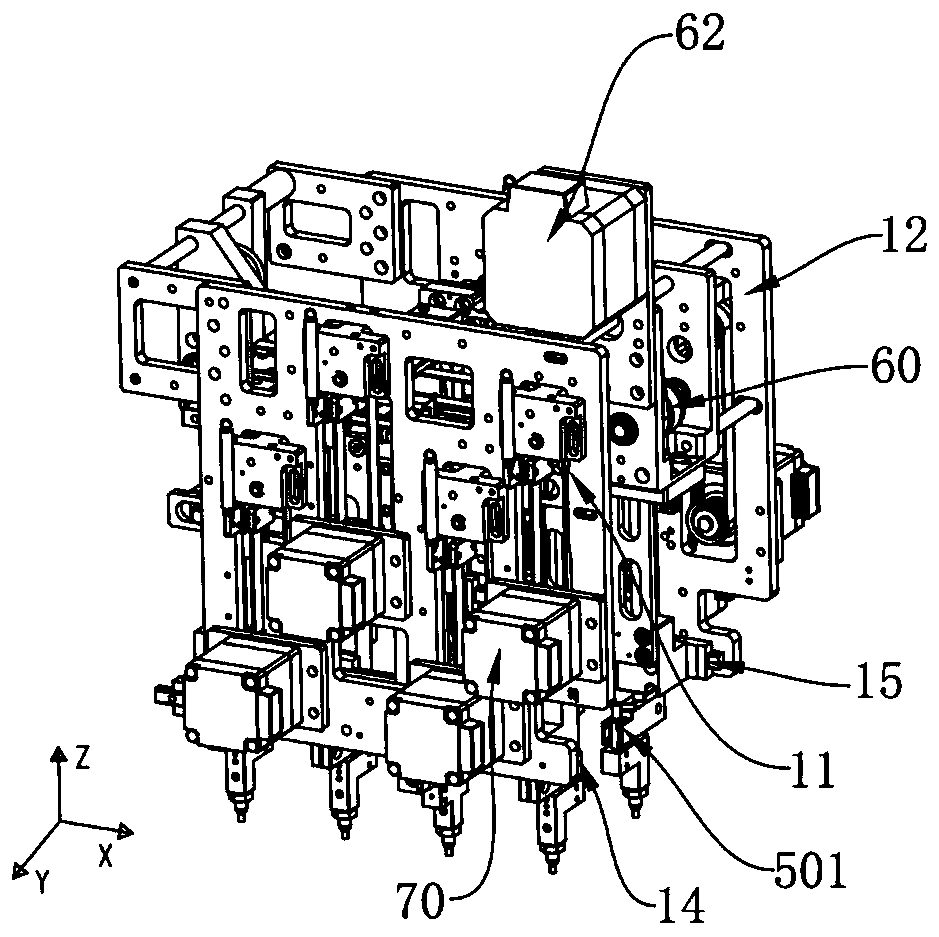
[0042] combine Figure 1-12 As shown, it schematically shows an integrated circuit material pick-and-place d...


PUM


Abstract

The invention relates to the technical field of material grabbing and putting, and discloses an integrated circuit material grabbing and putting device. The device comprises a gripper module, a firstrail arranged in the horizontal direction and a first driving mechanism used for driving the gripper module to do linear sliding along the first rail, the gripper module is used for grabbing the material, a second driving mechanism drives grabbing mechanisms to do linear sliding along a second rail, and therefore according to the material placing interval, the relative distance between the grabbing mechanisms is changed to precisely and rapidly grab the material, furthermore, each grabbing mechanism comprises two grabbing units located on the two sides of the second rail, each grabbing unit isdriven by a lifting mechanism to lift up and down to meet the material circulation grabbing and putting needs, the two grabbing units of the same grabbing mechanism can synchronously slide, the interval adjusting efficiency between the grabbing units is improved, the material circulation speed and the production efficiency can be improved, the adjusting precision is ensured, and the structural arranging is simplified.

Description

technical field [0001] The invention relates to the technical field of picking and placing materials, in particular to an integrated circuit material picking and placing device. Background technique [0002] At present, the pick-and-place process of materials is very common in the production and movement of various small regular materials such as IC chips, tablets, and hardware. Placed in another location, such as semiconductor chips often need to be grabbed from a matrix tray of one specification and placed accurately on a matrix tray of another specification; Pick and place the material tray of another specification into the material slot of another specification for packaging; another example is in the production and packaging process of hardware, the material pick and place transfer will also be used. [0003] During the production and processing of various small regular materials, a lot of work is required for pick-and-place handling. Currently, the gripper devices use...

Claims


Application Information

Patent Timeline
Patent Type & Authority Applications(China)
IPC IPC(8): B65G47/91B65G35/00
Inventor 林宜龙刘飞王轶云张宋儿黄宏裕林清岚黄理声
Owner 深圳格芯集成电路装备有限公司
Why Eureka
Try Eureka