
Turbulent flow column structure used for reinforced heat exchange of turbine blade

A technology that enhances heat transfer and turbine blades, and is applied to blade support components, engine components, machines/engines, etc. It can solve problems such as the deterioration of the working environment of high-temperature components, improve heat transfer performance, reduce pressure loss, and increase turbulence Effect

Pending Publication Date: 2019-06-28
NANJING UNIV OF AERONAUTICS & ASTRONAUTICS
View PDF0 Cites 8 Cited by
  • Summary
  • Abstract
  • Description
  • Claims
  • Application Information

AI Technical Summary

Problems solved by technology

The increasing gas temperature has seriously deteriorated the working environment of the high temperature components of the gas turbine power plant

Method used


Image

  • Turbulent flow column structure used for reinforced heat exchange of turbine blade
  • Turbulent flow column structure used for reinforced heat exchange of turbine blade

Examples


Embodiment Construction

[0021] Below in conjunction with embodiment the present invention will be further described.

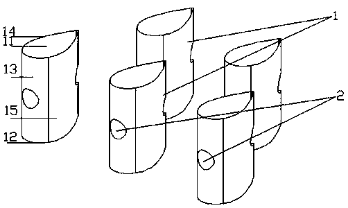
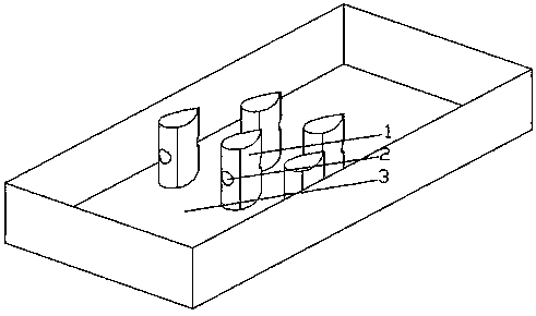
[0022] Such as figure 1 and 2 As shown, a spoiler column structure for enhanced heat transfer of turbine blades includes a spoiler column body 1, the spoiler column body 1 is a column with a drop-shaped cross section, and one end of the drop-shaped shape is a circular arc end, the other end is the apex end, the spoiler body 1 is provided with a penetration hole 2 that runs through the drop-shaped arc end and the apex end transversely, and the penetration hole 2 is located in the longitudinal center of the spoiler body 1 high.

[0023] Preferably, there is only one penetration hole 2 on the spoiler body 1 .

[0024] Specifically, the penetration hole 2 is a horizontally arranged cylindrical through hole, the central axis of the penetration hole 2 is perpendicular to the longitudinal direction of the spoiler column 1 body, and the central axis of the penetration hole 2 is in line wi...


PUM


Abstract

The invention discloses a turbulent flow column structure used for reinforced heat exchange of a turbine blade. The turbulent flow column structure comprises a turbulent flow column body. The turbulent flow column body is a column body with the cross section being of a water drop shape. One end of the water drop shape is an arc end. The other end of the water drop shape is a vertex end. The turbulent flow column body is provided with a penetrating hole transversely penetrating through the arc end and the vertex end of the water drop shape. The penetrating hole is located in the longitudinal center height of the turbulent flow column body. Compared with a traditional turbulent flow column, on one hand, a part of gas directly penetrates through the turbulent flow column through the penetrating hole, and can pass through the turbulent flow column more smoothly, and thus the pressure loss of the gas is reduced; on the other hand, the gas flows through the penetrating hole and flows out ofthe penetrating hole and then is mixed with wake gas flow of the turbulent flow column of the water drop shape, the turbulence degree of the gas is improved, thus the heat transfer performance is improved, and the heat transfer characteristic of the turbine blade is reinforced.

Description

technical field [0001] The invention belongs to the technical field of enhanced heat exchange of turbine blades of gas turbines (including ground gas turbines and aeroengines), and particularly relates to a spoiler column structure for enhanced heat exchange of turbine blades. Background technique [0002] Due to its small size, fast response, high efficiency, and high power, gas turbines are currently widely used in aerospace, ships, power plants, and other industrial fields. Improving the turbine inlet temperature of a gas turbine is one of the key technologies to improve the performance of a gas turbine. The increasing gas temperature seriously deteriorates the working environment of the high temperature components of the gas turbine power plant. High-efficiency cooling technology can prolong the service life of heated components, use more economical materials to reduce costs, and can effectively reduce the amount of cooling air and reduce engine power loss to improve en...

Claims


Application Information

Patent Timeline
Patent Type & Authority Applications(China)
IPC IPC(8): F01D5/18
Inventor 王锁芳张凯郝媛慧侯晓亭
Owner NANJING UNIV OF AERONAUTICS & ASTRONAUTICS
Learn More