A circulating pump for cpu water cooling system

A technology of water cooling system and circulation pump, which is applied in the direction of pumps, pump control, pump components, etc. It can solve the problems of low output flow and pressure accuracy, limited fluid pressure and fluid circulation capacity, pump output flow and pressure drop, etc., to achieve Large volumetric energy density and output flow, improved output capability and control accuracy, and high output efficiency

Active Publication Date: 2020-06-30
CHONGQING WANLI LIANXING IND GROUP
View PDF17 Cites 0 Cited by
  • Summary
  • Abstract
  • Description
  • Claims
  • Application Information

AI Technical Summary

Problems solved by technology

Due to the limited fluid pressure and fluid circulation capacity formed by the proposed micro fan and micro pumping system, and the unsatisfactory heat dissipation and cooling effect, there are certain limitations in practical application. The pressure is greatly affected by the working conditions. Fluid viscosity, temperature and output pressure affect the resonant frequency of the pump by affecting the system damping. When the resonant frequency of the piezoelectric vibrator under specific working conditions deviates greatly from the set excitation frequency, The output flow and pressure of the pump will drop significantly
Therefore, the output performance of the piezoelectric pump at a fixed frequency is not ideal, and the accuracy of the output flow and pressure calculated according to the set driving voltage and frequency is also low; in addition, most of the existing piezoelectric pumps use cantilever beam type The cut-off valve has poor flatness and cut-off effect, which seriously affects the output flow and pressure of the pump

Method used


Image

  • A circulating pump for cpu water cooling system
  • A circulating pump for cpu water cooling system
  • A circulating pump for cpu water cooling system

Examples


Embodiment Construction

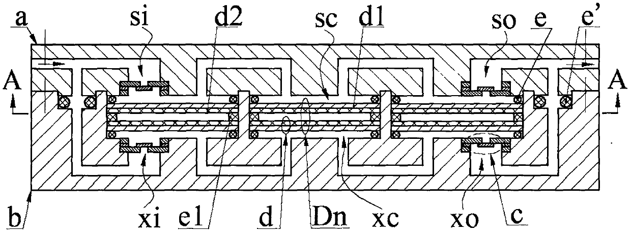
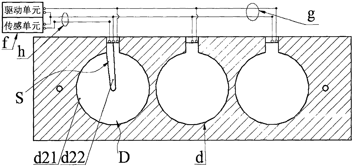
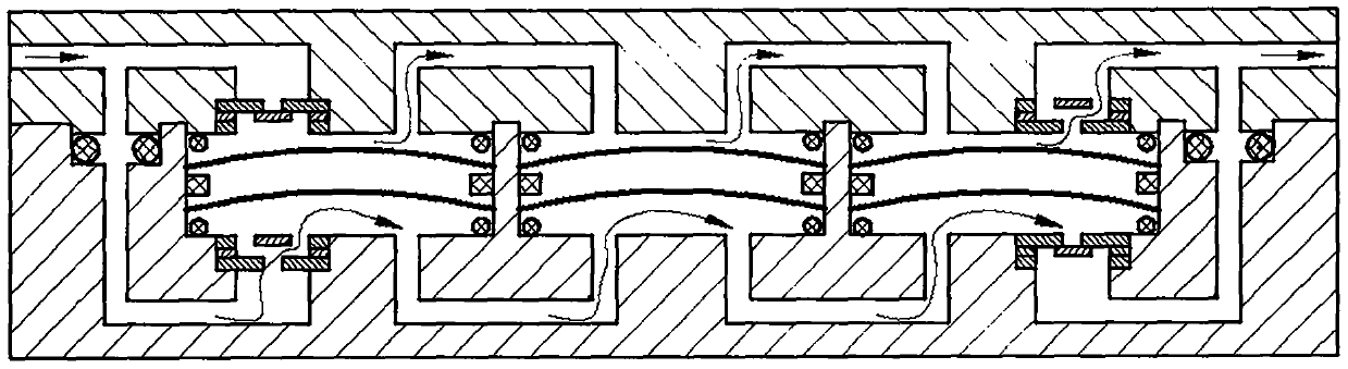
[0020]A CPU water-cooling system circulating pump of the present invention consists of a pump cover a, a pump body b, a disc valve c, a transducer Dn, a sealing ring e, an O-ring e', a power supply f, a lead group one g and a lead group two h constitutes. The pump cover a is provided with an inlet ai, an outlet ao, a left boss a3 with an upper inlet a1, a right boss a4 with an upper outlet a2, and at least two body platforms a5. An upper inlet a7 and an upper outlet a8 are provided, an upper inlet a9 and an upper outlet a10 are arranged on the rightmost body platform a5, and an upper inlet a9 and an upper outlet a8 are arranged on the rest of the body platform a5; an upper inlet a7 and an upper inlet hole a1 is in communication with inlet ai, upper outlet a10 and upper outlet a2 are in communication with outlet ao, two adjacent upper inlets a9 and upper outlet a8 are connected; pump body b is provided with left cavity b3 and right cavity b4 and the body cavity b5 which has th...


PUM


Abstract

The invention belongs to the technical field of heat dissipation and cooling and particularly relates to a CUP water cooling system circulation pump. A pump cover is arranged on a pump body, and inletvalves and outlet valves are arranged on the pump cover and the pump body. The inlet valves and the outlet valves are butterfly valves. Transducers are connected in a pump body cavity through pump cover body tables and sealing rings, and each transducer is composed of an elastic ring and piezoelectric vibrators stuck to the two sides of the elastic ring. Each piezoelectric vibrator is formed by connecting a base plate and piezoelectric pieces in a sticking manner. Upper pump cavities are formed by the transducers and the pump cover, and lower pump cavities are formed by the sealing rings andthe pump body. The upper pump cavities which are connected in parallel are then in parallel connection with the lower pump cavities which are connected in parallel. At least one piezoelectric vibratorcomprises a driver and a sensor. A power source outputs the same direct-current drive voltage signal to all the piezoelectric vibrators and the drivers, a sensing voltage signal generated by the sensor is used for judging the deformation state of the piezoelectric vibrators, when the sensing voltage reaches the extreme value, the power source drives the voltage and the piezoelectric vibrators tochange deformation directions, and therefore reciprocating bending vibration of the piezoelectric vibrators and one-direction flowing of fluids are achieved.

Description

technical field [0001] The invention belongs to the technical field of heat dissipation and cooling, and in particular relates to a circulation pump for a CPU water cooling system. Background technique [0002] In recent years, with the improvement of the integration and miniaturization of sub-products, as well as the continuous improvement of the operating speed and configuration density of electronic components such as chips and integrated circuits, the internal ventilation performance of electronic equipment is continuously declining, and the development of electronic components The heat is constantly rising, and cooling methods such as traditional fans and external heat sinks can no longer meet the actual needs. The cooling and heat dissipation effect of the internal components of electronic equipment has become a key factor restricting its reliability and operational stability. Based on this, people have successively proposed a variety of new air-cooled and water-cooled...

Claims


Application Information

Patent Timeline
Patent Type & Authority Patents(China)
IPC IPC(8): F04B43/04F04B49/06F04B49/22F04B53/10
Inventor 吴鸣黄鑫何晨阳丁璐瑶张忠华林仕杰王淑云
Owner CHONGQING WANLI LIANXING IND GROUP
Why Eureka
Try Eureka