Gearbox of speed changing mechanism

A technology of speed change mechanism and gearbox, which is applied in the direction of gear transmission, belt/chain/gear, mechanical equipment, etc. It can solve the problems affecting the stability of the output shaft, shock and vibration, etc., and achieve the effect of ensuring smooth operation

Inactive Publication Date: 2019-06-28
SHAOXING KEQIAO TONGYI SCI & TECH INFORMATION CONSULTING CO LTD
View PDF0 Cites 0 Cited by
  • Summary
  • Abstract
  • Description
  • Claims
  • Application Information

AI Technical Summary

Problems solved by technology

The resultant force of F1 and F2 changes periodically, which brings shock and vibration, which will affect the stability of the output shaft, and urgently needs improvement.

Method used


Image

  • Gearbox of speed changing mechanism
  • Gearbox of speed changing mechanism
  • Gearbox of speed changing mechanism

Examples


Embodiment Construction

[0014] The technical solutions of the present invention will be further specifically described below through the embodiments and in conjunction with the accompanying drawings.

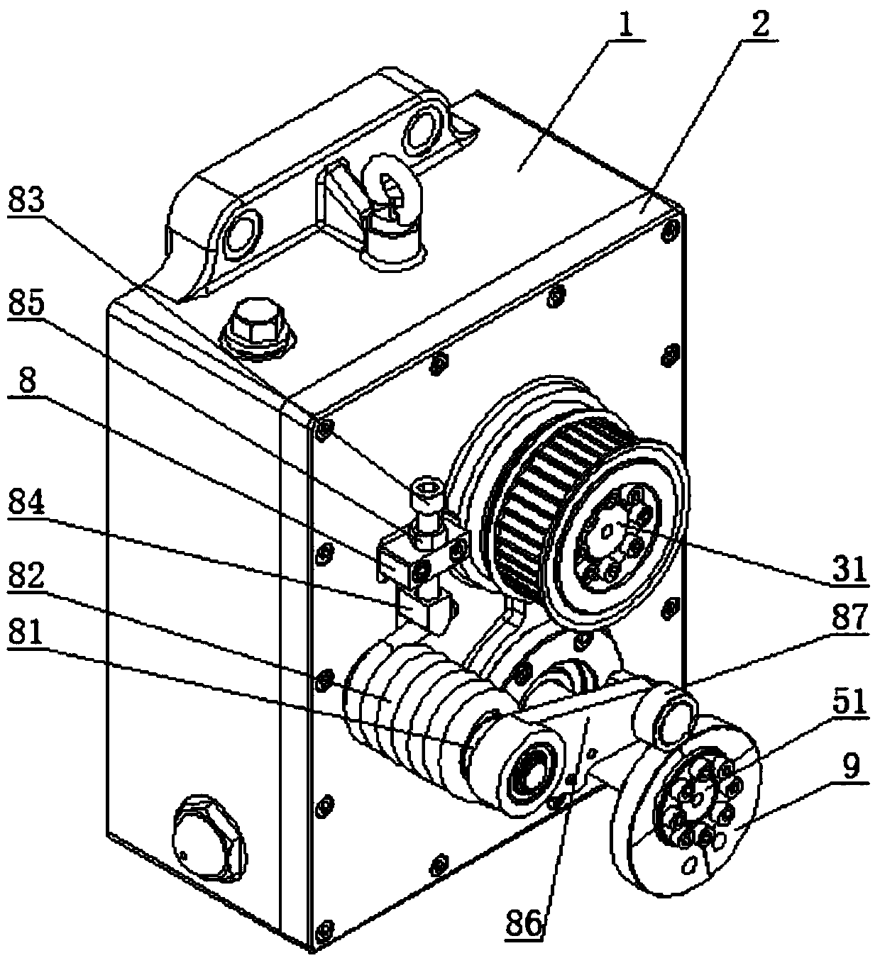
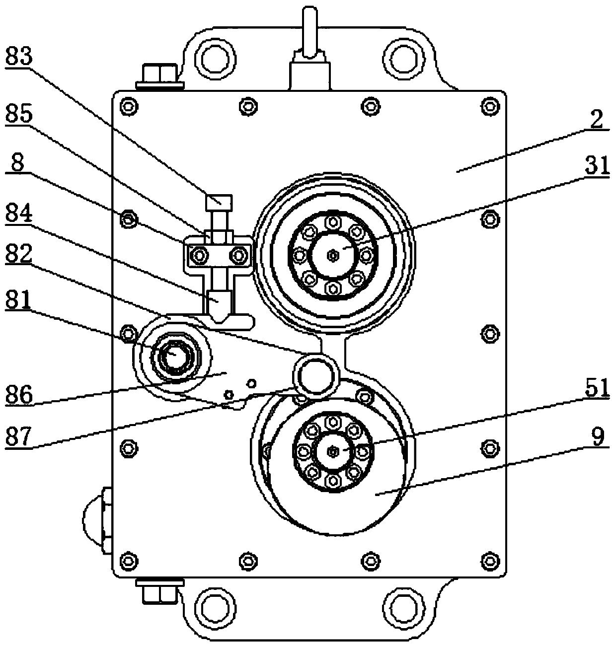
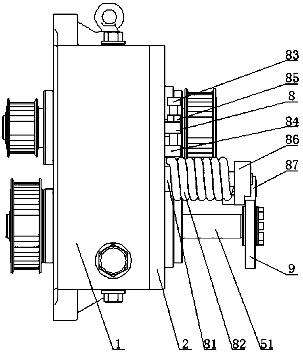
[0015] Such as Figure 1 to Figure 4 As shown, the gear box of the speed change mechanism includes a box body 1 and a box cover 2, and the inside of the box body 1 is provided with a driving gear 3, a bridge gear 4 and a driven gear 5, and the driving gear 3 and the bridge gear 4 mesh , the driving gear 3 is an eccentric gear, the driving shaft 31 is pierced on the driving gear 3, the bridge gear 4 and the driven gear 5 are meshed, the driven gear 5 is pierced with a driven shaft 51, and the driving gear 3 The center distance between the bridge gear 4 and the bridge gear 4 is constrained by the first connecting rod 6, and the center distance between the bridge gear 4 and the driven gear 5 is constrained by the second connecting rod 7, which ensures reliable operation between the gears.

[0016] The ca...


PUM


Abstract

The invention discloses a gearbox of a speed changing mechanism. The gearbox comprises a box body and a box cover; a driving gear, an intermediate gear and a driven gear are arranged in the box body;the driving gear meshes with the intermediate gear; the driving gear is an eccentric gear; a driving shaft penetrates through the driving gear; the intermediate gear meshes with the driven gear; a driven shaft penetrates through the driven gear; the center distance of the driving gear and the intermediate gear is restrained by a first connecting rod; the center distance of the intermediate gear and the driven gear is restrained by a second connecting rod; the end, located on the box cover side, of the driven shaft is sleeved with a cam; a shock absorbing device matched with the cam is arrangedon the box cover and comprises a support shaft, a spring, a screw, a swinging rod and a roller; one end of the spring is fixed through the screw, and the other end is fixed to one end of the swingingrod through welding; the roller is arranged at the other end, opposite to the end connected with the spring, of the swinging rod; and the outer circumferential surface of the roller is matched with the outer circumferential surface of the cam in a contact manner. By the aid of the gearbox, the unbalanced force during speed changing can be balanced, so that stable operation of the gearbox is guaranteed.

Description

technical field [0001] The invention relates to a mechanical transmission mechanism, in particular to a gear box of a speed change mechanism. Background technique [0002] The existing gear box of the speed change mechanism is actually a combination of a four-bar mechanism and a gear pair. When the driving gear rotates at a constant speed, because it rotates eccentrically, the angular velocity remains unchanged, the radius changes, and the linear velocity on the pitch circle changes accordingly. Let the speed of the bridge gear change, and then make the speed of the driven gear change through the meshing of the bridge gear and the driven gear, so as to realize the speed change. [0003] Shock and vibration will be brought about during the speed change, and the stability of the gearbox will be seriously affected during high-speed rotation. From the static analysis, there is gravity in the driving gear, bridge gear and connecting rod, and these forces are transmitted to the ge...

Claims


Application Information

Patent Timeline
IPC IPC(8): F16H1/22F16H57/00F16F7/00
Inventor 王立明
Owner SHAOXING KEQIAO TONGYI SCI & TECH INFORMATION CONSULTING CO LTD
Why Eureka
Try Eureka