Heat dissipating sheet and temperature regulating device

A technology of temperature regulating device and heat sink, applied in heat exchange equipment, heat exchanger shell, lighting and heating equipment, etc., can solve the problems of poor heat flow, poor adaptability, complicated manufacturing process, etc. Structural stability, good heat flow effect, and the effect of increasing the contact area

Pending Publication Date: 2019-06-28
GRAHOPE NEW MATERIALS TECH INC
View PDF0 Cites 0 Cited by
  • Summary
  • Abstract
  • Description
  • Claims
  • Application Information

AI Technical Summary

Problems solved by technology

[0003] The existing heat sink has a simple structure and poor heat flow, and the structure with good heat flow is more complicated and the manufacturing process is complicated
Moreover, the heat sink is finalized after forming, and the heat sink cannot be assembled and disassembled flexibly. The structure and size are relatively single, and the adaptability is poor.

Method used


Image

  • Heat dissipating sheet and temperature regulating device
  • Heat dissipating sheet and temperature regulating device
  • Heat dissipating sheet and temperature regulating device

Examples


Embodiment 1

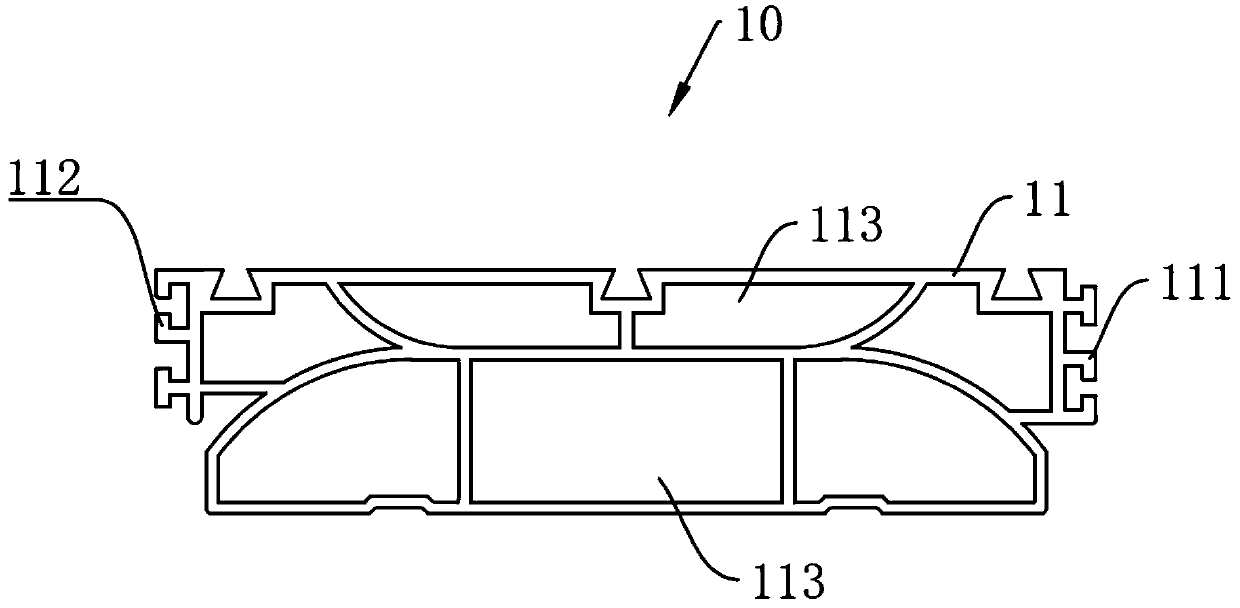
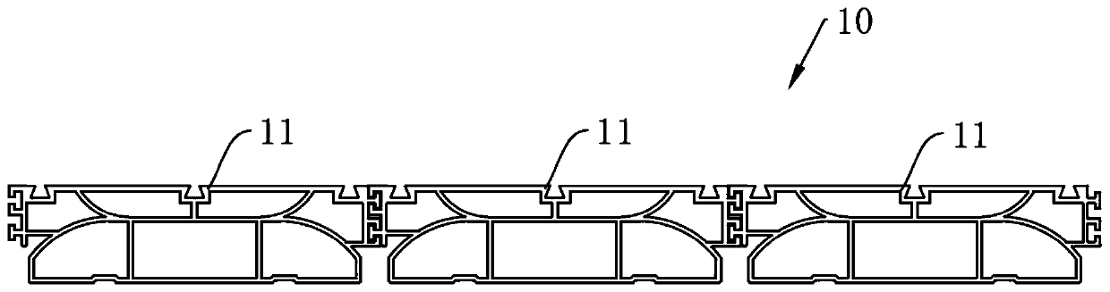
[0063] Please also refer to figure 1 and figure 2 , this embodiment provides a heat sink 10, which can be applied to the outside or surface of various objects that need heat exchange, thereby accelerating the heat exchange efficiency of the object and rapidly dissipating the heat of the object. It includes a heat sink body 11, There is at least one heat sink body 11 . The heat sink body 11 is formed with a convection chamber 113 penetrating therethrough, and a first connecting portion 111 and a second connecting portion 112 that cooperate with each other are formed on both sides, and the first connecting portion 111 can be passed between the two heat sink bodies 11 It is connected with the second connecting portion 112 .

[0064] The heat sink body 11 is in the shape of a sheet. In this embodiment, it is a straight rectangular sheet / plate. In other embodiments, the heat sink body 11 may be a sheet with a curved surface or a bent surface. The convection cavity 113 on the he...

Embodiment 2

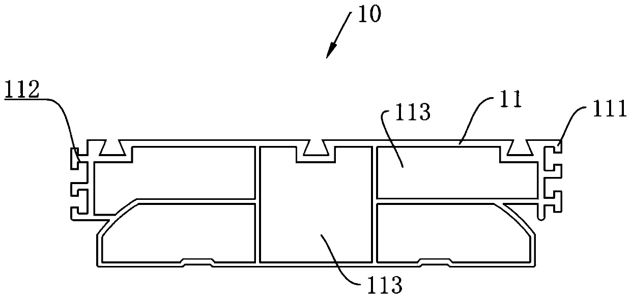
[0083] Please also refer to Figure 4 and Figure 5 The difference between the heat sink 10 of this embodiment and the body of the heat sink 10 of Embodiment 1 is that, in addition to the convection cavity 113, a plurality of heat dissipation fins 114 are formed on the heat dissipation fin body 11, and the extension of the heat dissipation fins 114 is consistent with The convection chambers 113 extend in the same direction.

[0084] In this way, the heat sink body 11 can not only have better heat flow, but also have a larger heat dissipation area, and can maximize the heat flux and heat radiation effect in a limited area. In this case, no heat build-up will occur. The heat sink body 11 has the same cross-section in the length direction, and can be integrally formed by extrusion, so that the processability is better.

[0085] The structure of the heat sink body in this embodiment is as follows: remove the outer wall of the first layer of the three convection chambers 113 of ...

Embodiment 3

[0089] Please also refer to Figure 6 to Figure 8 In addition to the heat sink body 11 and / or the heat sink body 11 of Embodiment 1 and / or the heat sink body 11 of Embodiment 2, the heat sink 10 of this embodiment also includes a functional barrier 12, and a first connecting portion is provided on both sides of the functional barrier 12 111 and the second connection part 112.

[0090]In this way, the functional barrier 12 can be spliced ​​with the heat sink body 11, and the functional barrier 12 connected to the heat sink body 11 can be used as an extension and combination to expand the space, and can also be used as a fixed load-bearing component.


PUM


Abstract

The invention provides a heat dissipating sheet and a temperature regulating device. The heat dissipating sheet comprises heat dissipating sheet bodies which are metal components, wherein a convectioncavity which is through in each heat dissipating sheet body is formed on the corresponding heat dissipating sheet body, and connecting parts which are matched with each other are formed at the two sides of each heat dissipating sheet body; and the two heat dissipating sheet bodies are connected through the connecting parts. The through convection cavities are arranged on the heat dissipating sheet bodies, so that the heat dissipating sheet has relatively good heat circulating effect while increasing the contact area with air, and heat collection is not generated. Modularized and various formcombination can be realized by splicing the heat dissipating bodies. The temperature regulating device comprises a temperature regulating part and two layers of stacked heat dissipating sheet bodies,wherein the two stacked heat dissipating sheet bodies are defined as one group; the heat dissipating sheet further can be spliced among groups; and the temperature regulating part is arranged betweentwo layers of the heat dissipating sheet bodies, so that the heat dissipating sheet can be subjected to active temperature regulation, and therefore, temperature regulating efficiency is relatively high.

Description

technical field [0001] The invention relates to the field of heat exchange devices, in particular to a heat sink and a temperature regulating device. Background technique [0002] The commonly used structure of heat sink is composed of heat dissipation main substrate and heat conduction fins. This structure can maximize the heat dissipation area in a limited volume and enhance the heat dissipation effect. [0003] The existing heat sink has a simple structure and poor heat flow, and a structure with good heat flow is relatively complicated, and the manufacturing process is complicated. Moreover, the heat sinks are finalized after forming, and the heat sinks cannot be flexibly assembled and disassembled. The structure and size are relatively single, and the adaptability is poor. Contents of the invention [0004] In view of this, the purpose of the present invention is to overcome the deficiencies in the prior art, and provide a heat sink and a temperature regulating devic...

Claims


Application Information

Patent Timeline
Patent Type & Authority Applications(China)
IPC IPC(8): F28F7/00F28F9/26F28F27/00
Inventor 张谦冯冠平李建英崔嘉袁凯杰
Owner GRAHOPE NEW MATERIALS TECH INC
Why Eureka
Try Eureka