Automation method for IMU-camera joint calibration

A joint calibration and IMU-based technology, applied in image data processing, instruments, calculations, etc., can solve problems that are not suitable for large-scale batch production, success and consistency are difficult to be guaranteed, and achieve low impact noise and simple operation Convenience and smooth movement

Active Publication Date: 2019-06-28
TZTEK TECH
View PDF4 Cites 10 Cited by
  • Summary
  • Abstract
  • Description
  • Claims
  • Application Information

AI Technical Summary

Problems solved by technology

The former is operated by people, and the success and consistency of the calibration are difficult to guarantee; the latter requires the driver or operator to remotely control the device to move, and to fully stimulate the six degrees of freedom of the IMU, it is important for the calibration site and motion trajectory. Strict requirements; neither is suitable for use in large-scale batch production

Method used


Image

  • Automation method for IMU-camera joint calibration

Examples


Embodiment Construction

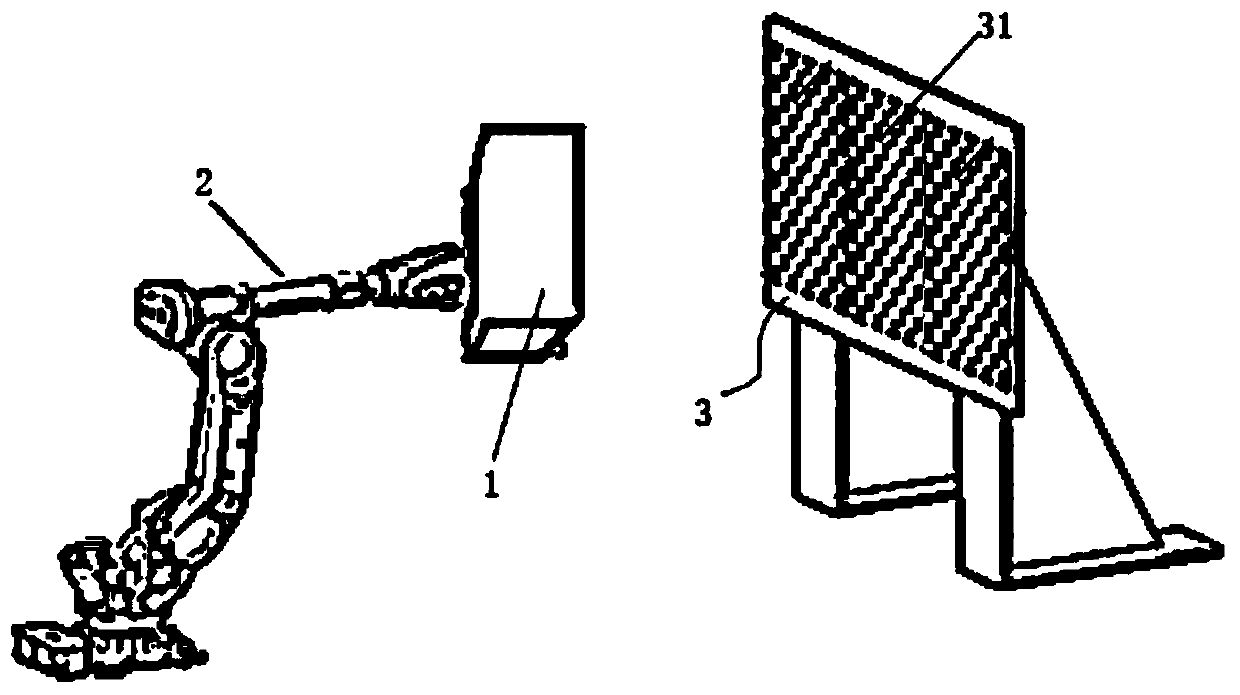
[0014] An automated method for joint IMU-camera calibration, see figure 1 : Install the IMU and camera on the equipment to be calibrated 1, and then fix the equipment to be calibrated 1 on the output end of the six-axis mechanical arm 2. In the initial state, a calibration plate 3 is set directly in front of the IMU and the camera to drive the six-axis mechanical arm The output end of the arm 2 drives the device 1 to be calibrated to move according to the set trajectory. During the movement, the calibration board 3 is within the field of view of the camera. During the movement, the original IMU data is collected and saved according to the IMU data output frequency, and at the same time press the The data output frequency collects and saves the camera image data, and then calculates the saved IMU raw data and camera image data through the kalibr toolbox to obtain the transformation matrix of the IMU coordinate system and the camera coordinate system, as well as the calibration e...


PUM


Abstract

The invention provides an automation method for IMU-camera joint calibration. The automation method for camera joint calibration provides full-automatic IMU-camera joint calibration method for unmanned equipment including an unmanned aerial vehicle, an unmanned vehicle and a mobile machine. According to the camera joint calibration method, IMU and camera can be conveniently calibrated in batch production. An IMU and a camera are installed on a to-be-calibrated device, fixing a device to be calibrated at the output end of the six-axis mechanical arm; a calibration plate is arranged right in front of the camera in an initial state; the output end of the six-axis mechanical arm is driven to drive the equipment to be calibrated to move according to a set track; the calibration plate is withinthe visual field range of the camera in the moving process; in the movement process, collecting and storing IMU original data according to the IMU data output frequency; and meanwhile, acquiring and storing camera image data according to the camera data output frequency, and then calculating the stored IMU original data and the camera image data through a kalibr tool box to obtain a transformationmatrix of an IMU coordinate system and a camera coordinate system, and a calibration error.

Description

technical field [0001] The invention relates to the technical field of automatic driving, in particular to an automatic method for IMU-camera joint calibration. Background technique [0002] In mobile robot systems such as UAVs and unmanned vehicles, SLAM (Simultaneous Localization and Mapping) technology is often used to realize the autonomous positioning and navigation of robots. Visual SLAM has problems such as low output frequency and easy positioning failure when rotating or moving at an accelerated rate, while IMU has the advantages of high output frequency and the ability to output 6 degrees of freedom measurement information; therefore, a research hotspot at this stage is to combine visual SLAM with IMU The obtained pose estimation results are fused to obtain more accurate output results. [0003] In the existing technology, when the MU and the camera are fused and calibrated, the existing technology collects the calibration data by means of moving the device for sm...

Claims


Application Information

Patent Timeline
Patent Type & Authority Applications(China)
IPC IPC(8): G06T7/80
Inventor 刘军传田乃鲁翁海峰刘克志
Owner TZTEK TECH
Why Eureka
Try Eureka