Multi-energy flow integrated power flow decoupling method based on energy hub in integrated energy system

A technology of integrated energy system and hub, which is applied in the field of power system and can solve the problems such as the inability of the system to work

Pending Publication Date: 2019-06-28
JIANGSU ELECTRIC POWER CO +2
View PDF2 Cites 7 Cited by
  • Summary
  • Abstract
  • Description
  • Claims
  • Application Information

AI Technical Summary

Problems solved by technology

However, when the two are coupled, an independent planning or operating approach may prevent the entire system from operating at its peak efficiency point
The growth of gas

Method used


Image

  • Multi-energy flow integrated power flow decoupling method based on energy hub in integrated energy system
  • Multi-energy flow integrated power flow decoupling method based on energy hub in integrated energy system
  • Multi-energy flow integrated power flow decoupling method based on energy hub in integrated energy system

Examples


Embodiment Construction

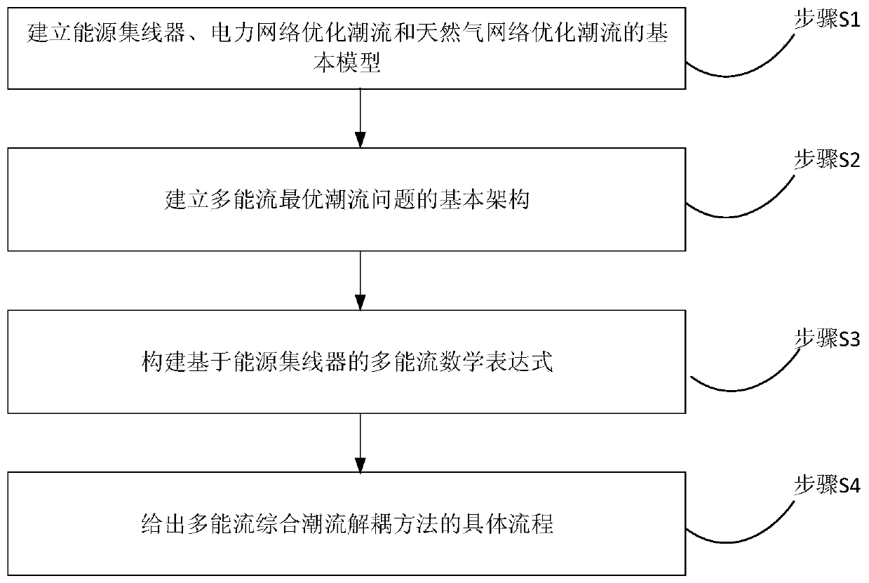
[0070] Such as figure 1 As shown, a decoupling method of multi-energy flow integrated power flow based on energy hub in the integrated energy system includes the following steps:

[0071] Step S1: Establish the basic models of energy hub, power network optimization power flow and natural gas network optimization power flow;

[0072] First, a basic model of the three needs to be established for subsequent use.

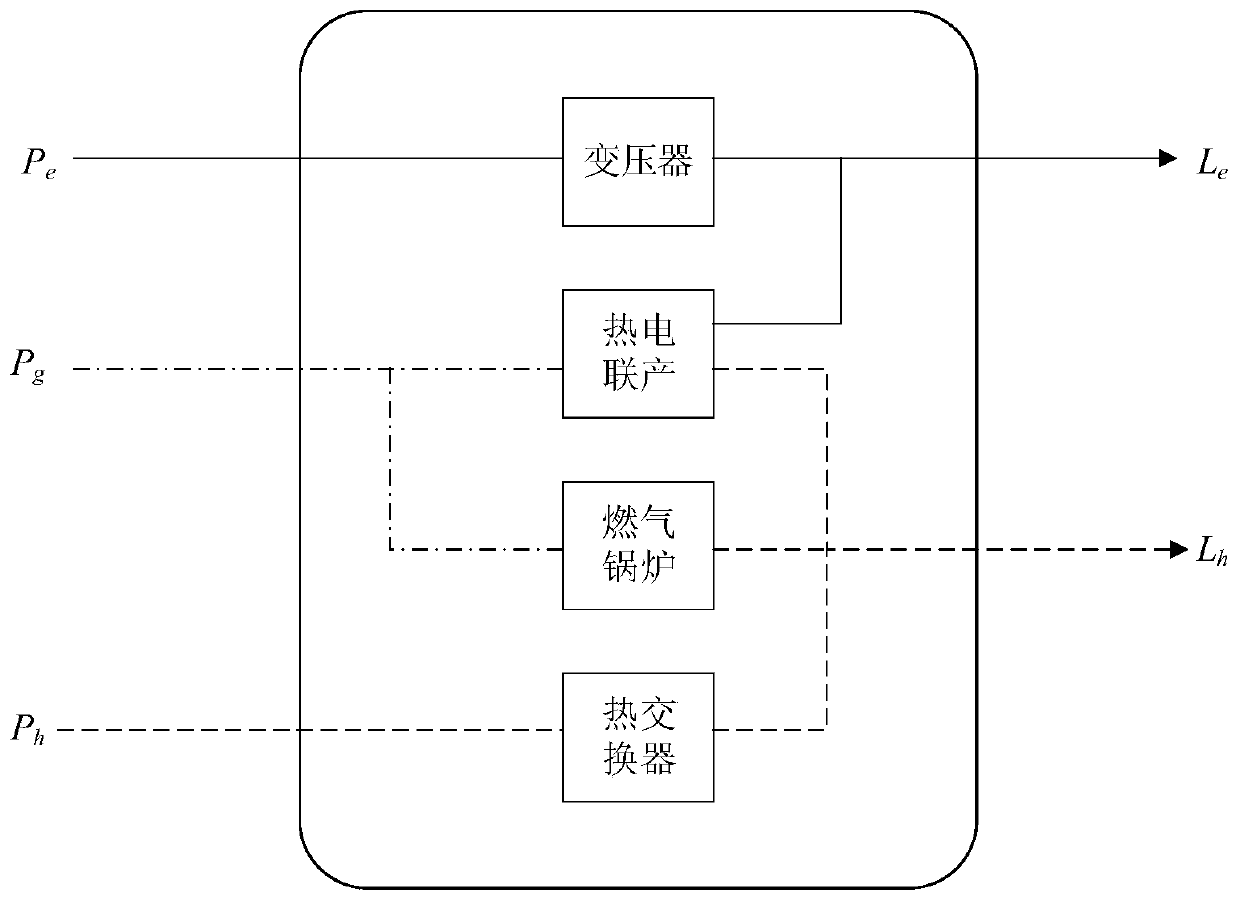
[0073] (1) Basic model of energy hub

[0074]

[0075]

[0076] In the formula, L is the energy output vector of the energy hub; L α , L β ,...,L ψ is the component of the vector; C is the coupling factor matrix; c α,α ,c β , α ,...,c ω,ψ is the element in the matrix; P is the energy input vector of the energy hub; P α ,P β ,...,P ψ Is the component of the vector; I is the number of energy carriers at the input end; O is the number of energy carriers at the output end.

[0077] For single-input-single-output energy hubs, the coupling factor represents ...


PUM


Abstract

The invention discloses a multi-energy flow integrated power flow decoupling method based on an energy hub in an integrated energy system. The method comprises the steps of (1) establishing basic models of the energy hub, a power network optimization power flow and a natural gas network optimization power flow, (2) establishing a basic architecture of a multi-energy flow optimal power flow problem, (3) constructing a multi-energy flow mathematical expression based on the energy hub, and (4) giving a specific flow of the multi-energy flow integrated power flow decoupling method. The invention decomposes the multi-energy flow optimal power flow problem into a traditional single-energy flow optimal power flow problem and maintains the characteristics of the synchronization analysis of an integrated energy system, and therefore, the multi-energy flow optimal power flow problem is solved well.

Description

technical field [0001] The invention relates to the technical field of power systems, in particular to an energy hub-based decoupling method for multi-energy flow integrated power flow in an integrated energy system. Background technique [0002] Up to now, the efficient operation of energy has been one of the difficulties that countries all over the world want to overcome. Energy networks in the traditional sense, such as electricity and gas infrastructure, are planned and operated separately. However, when the two are coupled, independent planning or operating methods may prevent the entire system from working at its peak efficiency point. The growth of gas and other distributed generation, especially combined heat and power and combined heating and cooling, poses challenges to the efficient operation of the system. Today, the integrated energy system can store and convert energy through the energy hub. The energy hub has a certain diversity in energy supply and energy s...

Claims


Application Information

Patent Timeline
IPC IPC(8): H02J3/06
Inventor 杨世海纪峰曹晓冬杨永标
Owner JIANGSU ELECTRIC POWER CO
Why Eureka
Try Eureka