Thermosyphon type defrosting dual-channel oil and gas recovery condensing unit

A technology of thermosyphon and condensing units, which is applied in the direction of refrigerators, refrigeration components, compressors, etc., can solve the problems of unsafe equipment and complex pipelines of the system, and achieve simple structure, improved stability, and high coldness Effect

Pending Publication Date: 2018-11-02
GUANGDONG SHENLING ENVIRONMENT SYST CO LTD
View PDF10 Cites 9 Cited by
  • Summary
  • Abstract
  • Description
  • Claims
  • Application Information

AI Technical Summary

Problems solved by technology

[0003] The patent application number 201210181207.4 provides a stepped refrigeration system and refrigeration method for oil and gas recovery. The defrosting method of the patent is: the refrigerant is compressed by the high-temperature first-stage compressor and then discharged into the high-temperature and high-pressure refrigerant, and then enters the four-way The A port of the reversing valve flows out through the D port, and the high-temperature and high-pressure refrigerant directly enters the first-stage oil-gas condenser, and exchanges heat with the low-temperature first-stage oil-gas condenser, so as to achieve the purpose of defrosting. This patent uses a four-way valve to replace In the heat pump method, the system piping is very complicated, and the defrosting temperature is too high. Since oil and gas are combustible gases, it is easy to cause unsafe equipment

Method used


Image

  • Thermosyphon type defrosting dual-channel oil and gas recovery condensing unit
  • Thermosyphon type defrosting dual-channel oil and gas recovery condensing unit
  • Thermosyphon type defrosting dual-channel oil and gas recovery condensing unit

Examples


Embodiment Construction

[0016] The present invention will be further described below in conjunction with the accompanying drawings.

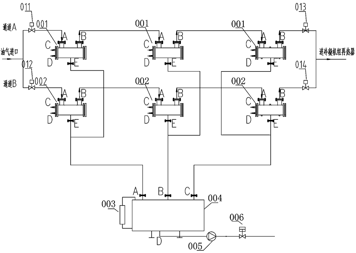
[0017] Such as figure 1 As shown, the dual-channel oil-gas switching and oil collection system includes a switching electric valve, a first evaporator 001, a second evaporator 002, an oil delivery pump 009, an electric valve 010, an oil storage tank 008 and a liquid level gauge 007. Among them, the oil and gas condensation is divided into two channels, A and B. Wherein, the switching electric valves on channel A are the first main valve 011 and the third main valve 013; the switching electric valves on channel B are the second main valve 012 and the fourth main valve 014. In channel A, the oil and gas pass through the first main valve 011, pass through three first evaporators 001 and the third main valve 013 in sequence, and then enter the oil and gas reheater of the condensing unit. In channel B, the oil and gas pass through the second main valve 012, pass through t...


PUM


Abstract

The invention provides a thermosyphon type defrosting dual-channel oil and gas recovery condensing unit. In a refrigeration system of each stage, a first compressor, a condenser, a first liquid accumulator, a thermosyphon heat exchanger, a first valve, a first expansion valve, a first evaporator, a second valve and a first gas-liquid separator are sequentially connected so as to form a first condensation loop; the thermosyphon heat exchanger, a third valve, the first evaporator and a fourth valve are sequentially connected so as to form a first thermosyphon loop. The evaporator of the refrigeration system is used for defrosting, and the temperature is basically maintained to be 30 DEG C, so that the safety of oil gas used as combustible gas can be improved. Furthermore, passive thermosyphon heat exchange is adopted, and internal circulation is performed by means of evaporation rise and condensation downflow, so that the cooling capacity inside the frost is brought to a liquid pipe. Furthermore, the superheat of the liquid pipe is improved, and the energy efficiency ratio of the refrigeration system is improved. A refrigerant bypass is not involved, so that little effect is caused on the performance of the refrigeration system.

Description

technical field [0001] The invention relates to the field of oil and gas recovery, in particular to a thermosiphon type defrosting double-channel oil and gas recovery condensing unit. Background technique [0002] To meet the oil and gas discharge standards stipulated by the state, oil and gas recovery and treatment devices must be installed to recover and process the light hydrocarbon components in oil and gas. The existing oil and gas treatment methods include condensation, absorption, adsorption and membrane methods. Among them, the condensation method is indispensable as a high-concentration pretreatment process in the oil and gas recovery process. However, due to the inconvenience of setting up a complex deconcentration component process before the oil and gas recovery, there will generally be frosting problems. For long-running oil and gas recovery occasions such as shipping and tank farms, the condensing unit needs to be designed to simultaneously condense and defrost...

Claims


Application Information

Patent Timeline
Patent Type & Authority Applications(China)
IPC IPC(8): F25B7/00F25B41/06F25B43/00F25B47/02F25B41/325
CPCF25B7/00F25B43/006F25B47/02F25B41/31
Inventor 王浩陈思思钟胜兵
Owner GUANGDONG SHENLING ENVIRONMENT SYST CO LTD
Why Eureka
Try Eureka