Permanent magnet synchronous motor position sensorless control based on non-singular terminal sliding mode
A permanent magnet synchronous motor, non-singular terminal technology, applied in motor generator control, electronic commutation motor control, control system and other directions, can solve the problem of low speed estimation accuracy, improve the rotor position and speed estimation accuracy, simplify The effect of designing, optimizing performance
- Summary
- Abstract
- Description
- Claims
- Application Information
AI Technical Summary
Problems solved by technology
Method used
Image

Examples
specific Embodiment approach 1
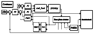
[0026] Specific implementation mode one: refer to figure 1 Specifically illustrate this embodiment, the non-singular terminal sliding mode based permanent magnet synchronous motor position sensorless control method described in this embodiment, the method includes the following steps:
[0027] Step 1. Design an integral nonsingular fast terminal sliding surface.
[0028] Step 2. According to the mathematical model of the surface-mounted permanent magnet synchronous motor in the two-phase stationary coordinate system, the sliding mode observer is designed.
[0029] Step 3. Design the control law of the terminal sliding mode observer in combination with the fast power reaching law.
[0030] Step 4. Perform stability analysis on the designed observer.
[0031] In this embodiment, the application proposes a design method of a new terminal sliding mode observer based on fast power reaching law. By designing a new type of integral non-singular fast terminal sliding mode surface an...
specific Embodiment approach 2
[0032] Specific embodiment 2: This embodiment is to further explain the position sensorless control of permanent magnet synchronous motor based on non-singular terminal sliding mode described in specific embodiment 1. In this embodiment, the integral non-singular The singular fast terminal sliding mode surface is:
[0033]
[0034] In the formula: b, c, r>0; x 1 is the state variable of the system.
specific Embodiment approach 3
[0035] Specific embodiment three: This embodiment is to further illustrate the non-singular terminal sliding mode based permanent magnet synchronous motor position sensorless control described in specific embodiment one. In this embodiment, step two is specifically implemented according to the following method:
[0036] The current state equation of the surface-mounted permanent magnet synchronous motor based on the stationary coordinate system is established as follows:
[0037]
[0038] In the formula, i α i β is the stator current; u α , u β is the stator voltage; E α ,E β for the extended back EMF.
[0039] According to the mathematical model of the surface-mounted permanent magnet synchronous motor in the two-phase stationary coordinate system, the sliding mode observer equation is constructed as follows:
[0040]
[0041] In the formula, is the observed value of the stator current; u α , u β is the control input of the observer.
PUM
 Abstract
Description
Claims
Application Information
 - R&D
- Intellectual Property
- Life Sciences
- Materials
- Tech Scout
- Unparalleled Data Quality
- Higher Quality Content
- 60% Fewer Hallucinations
Browse by: Latest US Patents, China's latest patents, Technical Efficacy Thesaurus, Application Domain, Technology Topic, Popular Technical Reports.
© 2025 PatSnap. All rights reserved.Legal|Privacy policy|Modern Slavery Act Transparency Statement|Sitemap|About US| Contact US: help@patsnap.com