Image transfer arrangement and method for image transfer

A technology of transmission device and image sensor, applied in image communication, applications, components of TV systems, etc., can solve the problems of image loss and image transmission, difficult to achieve delay-free and interference-free image transmission, etc., and achieve the effect of small delay

Active Publication Date: 2019-06-28
SCHOLLY FIBEROPTIC
View PDF19 Cites 2 Cited by
  • Summary
  • Abstract
  • Description
  • Claims
  • Application Information

AI Technical Summary

Problems solved by technology

Delay-free and interference-free image transmission is therefore difficult to achieve in practice
Especially in endoscopy applications where real-time images are transmitted for surgery, image transmission with delay or image loss is a big problem

Method used


Image

  • Image transfer arrangement and method for image transfer
  • Image transfer arrangement and method for image transfer
  • Image transfer arrangement and method for image transfer

Examples


Embodiment Construction

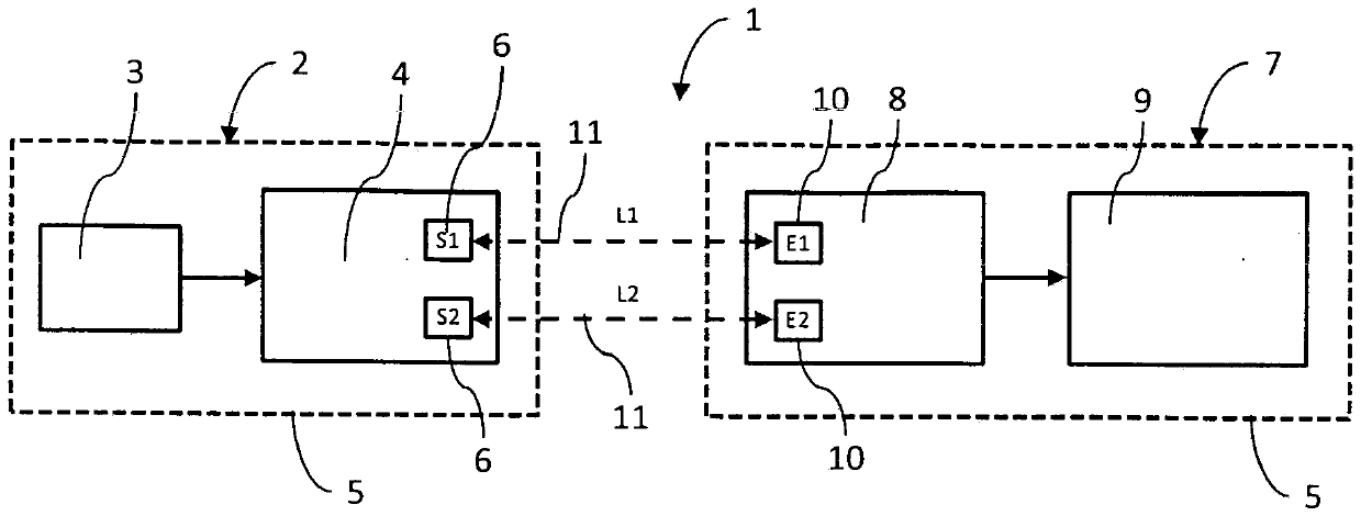
[0099] figure 1 A schematic block diagram of an image transmission device 1 according to the invention is shown. The image recording device 2 has an image sensor 3 and a transmitter unit 4 , which are integrated in one device in a common housing 5 .

[0100] The transmission unit 4 has two mutually independent transmission modules 6 as interface modules.

[0101] The image display device 7 has a receiving unit 8 and a screen 9 which is integrated with the receiving unit 8 in a housing 5 of the device.

[0102] The receiving unit 8 has two receiving modules 10 as interface modules, and the receiving modules combine with the sending module 6 of the sending unit 4 to form two physically separated communication channels 11 .

[0103] The communication channel 11 can be designed, for example, as an optical transmission path or as a radio interface. This can vary according to the specific field of application, and mixed forms are also possible.

[0104] In an advantageous exampl...


PUM


Abstract

The invention relates to an image transfer arrangement (1) for the wireless transfer of image information items between a transmitter (4) and a receiver (8), wherein at least two communication channels (11) which are physically independent of one another are formed between the transmitter (4) and the receiver (8) and enable impairment and interference-free communication.

Description

technical field [0001] The present invention relates to an image transmission device for wirelessly transmitting image information using a sending unit and a receiving unit. Background technique [0002] Such transmission devices are known in principle and are used in particular in endoscopy to transmit image data recorded by a camera to an image display device. The advantage of such a wireless image transmission device is that the individual devices can be arranged freely in space and that no cables interfere during actual work, for example during surgery. [0003] Devices for wireless image transmission are known in principle, the biggest issues here being the bandwidth and security of the transmission. Delay-free and interference-free image transmission is therefore difficult to achieve in practice. Especially in endoscopy applications where live images are transmitted for surgery, image transmission with delay or image loss is a big problem. Contents of the invention...

Claims


Application Information

Patent Timeline
Patent Type & Authority Applications(China)
IPC IPC(8): H04N7/18
CPCA61B1/00009A61B1/00016H04N23/555H04N23/60A61B1/00045
Inventor M·屈恩A·克勒S·施勒埃尔
Owner SCHOLLY FIBEROPTIC
Why Eureka
Try Eureka