
Oil sludge screening separating device suitable for coupling effect

A separation device and oil sludge technology, which is applied in the direction of filtration separation, separation method, mobile filter element filter, etc., can solve the problems of low oil sludge efficiency and inability to guarantee oil cleanliness, and achieve the effect of easy recycling

Pending Publication Date: 2019-07-02
HEILONGJIANG LANDE ULTRASONIC TECH CO LTD
View PDF6 Cites 4 Cited by
  • Summary
  • Abstract
  • Description
  • Claims
  • Application Information

AI Technical Summary

Problems solved by technology

However, the equipment has low efficiency in separating oil sludge and cannot guarantee the cleanliness of oil

Method used


Image

  • Oil sludge screening separating device suitable for coupling effect
  • Oil sludge screening separating device suitable for coupling effect
  • Oil sludge screening separating device suitable for coupling effect

Examples


specific Embodiment approach 1

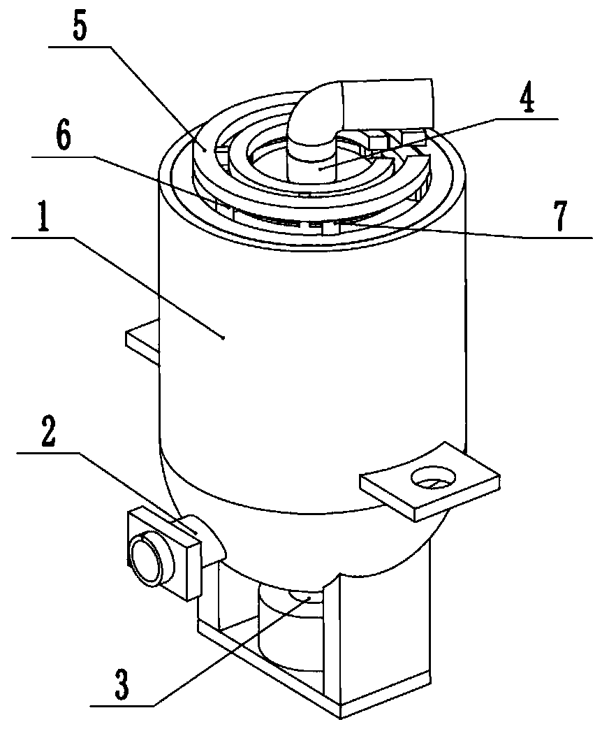
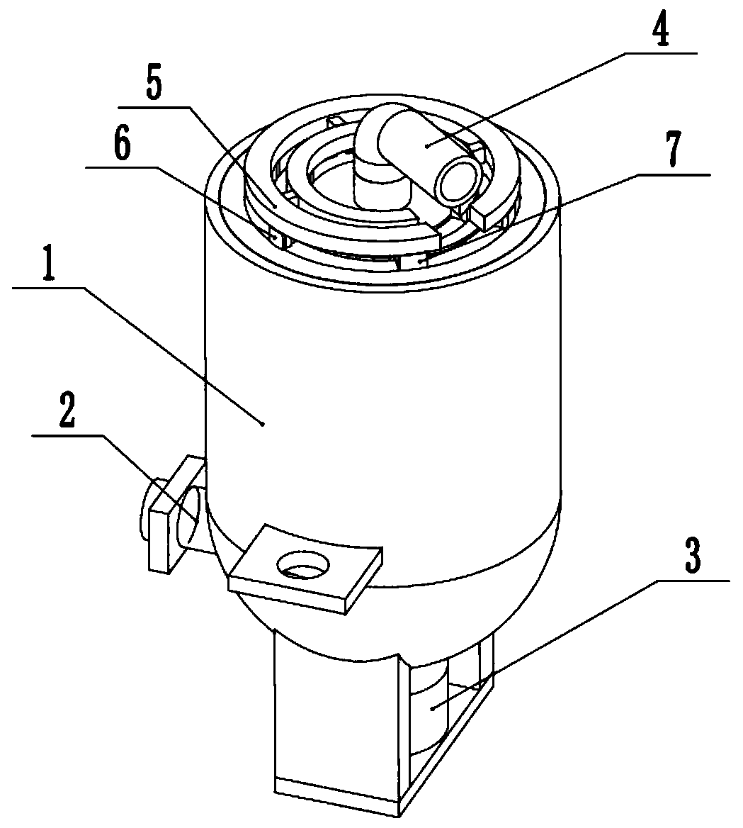
[0030] Such as Figure 1 to Figure 10 As shown in the figure, an oil sludge screening and separation device suitable for coupling, including a sieving fixed cylinder 1, an oil recovery pipe with a valve 2, a centrifugal drive 3, an oil sludge adder 4, a sludge recovery plate 5, and six sludge scrapers 6 and six mud recovery devices 7, the oil recovery pipe 2 with a valve is fixedly connected to the lower side of the left end of the sieve fixed cylinder 1, the oil recovery pipe 2 with a valve is connected to the inside of the sieve fixed cylinder 1, and the centrifugal drive The lower end of 3 is fixedly connected to the sieve-off fixed cylinder 1, the centrifugal driver 3 is rotatably connected in the sieve-off fixed cylinder 1, the oil sludge adder 4 is fixedly connected to the upper end of the sieve-off fixed cylinder 1, and the upper end of the centrifugal driver 3 is rotatably connected to the sludge In the adder 4 , the sludge recovery plate 5 is fit in the upper end of t...

specific Embodiment approach 2

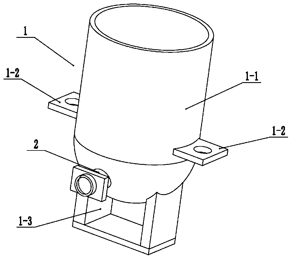
[0032] Such as Figure 1 to Figure 10As shown, this embodiment will further describe Embodiment 1. The described sieving and fixing cylinder 1 includes a sieving and separating cylinder body 1-1, two fixing plates 1-2 and a motor fixing seat 1-3, and two fixing plates 1 -2 are respectively fixedly connected to the two ends of the outer wall of the sieving cylinder 1-1, the two fixing plates 1-2 are provided with threaded holes, and the motor fixing seat 1-3 is fixedly connected to the lower end of the sieving cylinder 1-1 . The two fixing plates 1-2 fix the device by bottom corner bolts.

specific Embodiment approach 3

[0034] Such as Figure 1 to Figure 10 As shown, this embodiment will further explain the second embodiment. The centrifugal driver 3 includes a servo motor 3-1, a central rotating shaft 3-2, a precision separation screen filter cartridge 3-3, and a plurality of precision separation round holes 3- 4. Particle separation sieve cartridge 3-5 and multiple particle separation holes 3-6, servo motor 3-1 is fixedly connected in the motor fixing seat 1-3, the lower end of the central rotating shaft 3-2 is connected to the servo through a coupling The transmission shaft of the motor 3-1 and the central rotating shaft 3-2 are rotationally connected to the lower end of the sieving cylinder 1-1 through a mechanical seal, and the lower end of the precision separation sieve filter cartridge 3-3 is fixedly connected to the central rotating shaft 3-2. The separation screen filter cartridge 3-3 is provided with a plurality of penetrating precision separation circular holes 3-4, the lower end o...


PUM


Abstract

The invention belongs to the technical field of lubricating oil production, and more specifically relates to an oil sludge screening separating device suitable for coupling effect. The oil sludge screening separating device suitable for coupling effect comprises a screening separating fixed cylinder, an oil recycling pipe provided with a valve, a centrifugation driver, an oil sludge adding device,a sludge recovery plate, six sludge scraping recycling devices, and six sludge sweeping recycling devices; the oil recycling pipe provided with a valve is fixedly connected with the lower side of theleft end of the screening separating fixed cylinder, and is communicated with the internal part of the screening separating fixed cylinder; the lower end of the centrifugation driver is fixedly connected with the screening separating fixed cylinder, and the centrifugation driver is connected with the internal part of the screening separating fixed cylinder in rotation connection. The beneficial effects are that: centrifugation rotation is adopted, so that oil is discharged rapidly; a double-layer screening filtering cylinder is adopted for separation of sludge and oil; sludge on the screeningfiltering cylinder is scraped down for collection automatically; it is convenient for comprehensive recycling and utilization.

Description

technical field [0001] The invention relates to the field of lubricating oil production technology, in particular to an oil sludge screening and separation device suitable for coupling. Background technique [0002] Patent No. CN201611070729.1 discloses a centrifugal automatic oil sludge separator, including a horizontal drum, a protective cover is arranged outside the horizontal drum, the horizontal drum is connected to the hollow shaft of the power center at one end, and the dirty oil delivery pipe is installed at both ends. Bearings are installed in the hollow shaft of the power center, and the transmission and auxiliary power machines on the hollow shaft of the power center are connected. The safety door of the horizontal drum is equipped with a stepping oil scraping device and a stepping scraper shoveling device. Its advantage is that both the oil scraping device and the slag discharging device adopt step-by-step flow control to realize automatic control. However, the ...

Claims


Application Information

Patent Timeline
Patent Type & Authority Applications(China)
IPC IPC(8): B01D33/11B01D33/067B01D33/42B01D33/46B01D33/72B01D33/80
CPCB01D33/11B01D33/067B01D33/42B01D33/801B01D33/72B01D33/466
Inventor 关丽娜赵晨曦张剑锋陈光甡张修全赵宪忠黄滨
Owner HEILONGJIANG LANDE ULTRASONIC TECH CO LTD
Learn More