
Automatic pin-shearing bending device

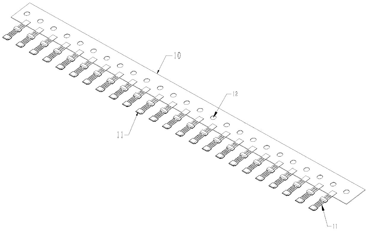
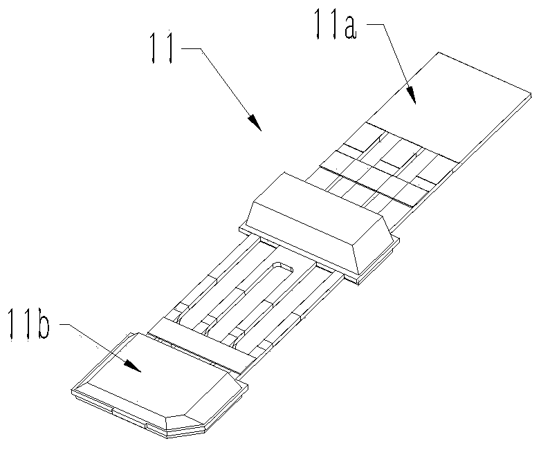
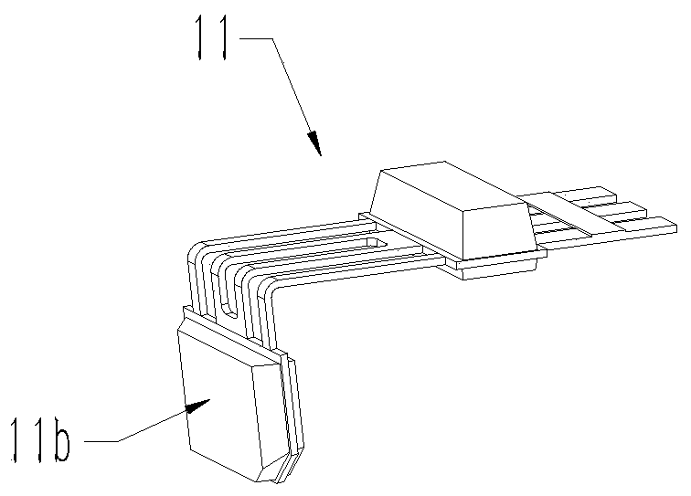
A cutting and automatic technology, which is applied in the field of automatic cutting and bending equipment, can solve the problems of difficulty in controlling the strength of workers, difficulty in controlling the distance between sections, and high economic costs.

Active Publication Date: 2019-07-02
苏州英维特精密机械有限公司
View PDF10 Cites 8 Cited by
  • Summary
  • Abstract
  • Description
  • Claims
  • Application Information

AI Technical Summary

Problems solved by technology

The old device needs to be bent manually with pin forming pliers. It is difficult to control the distance between the bent sections. It is difficult to meet customers with high size requirements. It is difficult to control the strength of the workers. The pins are easy to be broken during the shaping process. , the hands hold the pliers tightly, and the work efficiency is low. It belongs to an integrated design. It needs to be replaced as a whole when it is worn and processed for new models, and the economic cost is high. Therefore, there is an urgent need for an automatic cutting and bending equipment to figure 1 Bending and cutting the IC chip in

Method used


Image

  • Automatic pin-shearing bending device
  • Automatic pin-shearing bending device
  • Automatic pin-shearing bending device

Examples


Embodiment Construction

[0035] The preferred embodiments of the present invention will be described in detail below in conjunction with the accompanying drawings, so that the advantages and features of the present invention can be more easily understood by those skilled in the art, so as to define the protection scope of the present invention more clearly.

[0036] See attached Figure 19 , 20As shown, a kind of automatic shearing and bending equipment of this embodiment includes a coil feeding platform 20 arranged on a workbench 100, a coil feeding power assembly 30, a single IC chip cutting assembly 50, and a jaw cylinder assembly 60 , scissor foot bending positioning assembly 70, scissor foot assembly 80, bending assembly 90, coil feed platform 20 is flush with the positioning platform 71 of scissor foot bend positioning assembly 70, and coil feed platform 20 is used to store a plurality of The coil material 10 of the IC chip 11 is passed through, the coil material feeding power assembly 30 and t...


PUM


Abstract

The invention discloses an automatic pin-shearing bending device. The automatic pin-shearing bending device includes a coil stock feeding platform arranged on a working table, a coil stock feeding power assembly, a single integrated circuit (IC) chip cutting assembly, a clamping jaw air cylinder assembly, a pin-shearing bending positioning assembly, a pin-shearing assembly and a bending assembly,the coil stock feeding power assembly and the single IC chip cutting assembly are both arranged on the upper part of the coil stock feeding platform, the coil stock feeding power assembly is used forallowing coil stocks to move towards a positioning platform, the single IC chip cutting assembly is used for cutting single IC chips on the coil stocks, the pin-shearing assembly and the bending assembly are arranged at the two ends above the positioning platform correspondingly, the clamping jaw air cylinder assembly is used for grabbing the cut single IC chips onto the positioning platform, thepin-shearing bending positioning assembly positions the cut single IC chips, and the pin-shearing assembly and the bending assembly shear and bend the two ends of the single IC chips correspondingly.The automatic pin-shearing bending device can realize the length of pins of the IC chips on a large scale quickly according to the actual use needs.

Description

technical field [0001] The invention relates to an automatic scissors and bending equipment. Background technique [0002] At present, IC chip pin processing needs to be figure 2 One end of the IC chip is cut and the other end is bent to form image 3 in the structure. The old device needs to be bent manually with pin forming pliers. It is difficult to control the distance between the bent sections. It is difficult to meet customers with high size requirements. It is difficult to control the strength of the workers. The pins are easy to be broken during the shaping process. , the hands hold the pliers tightly, and the work efficiency is low. It belongs to an integrated design. It needs to be replaced as a whole when it is worn and processed for new models, and the economic cost is high. Therefore, there is an urgent need for an automatic cutting and bending equipment to figure 1 The IC chip in it is bent and cut. Contents of the invention [0003] In order to overcome...

Claims


Application Information

Patent Timeline
IPC IPC(8): B21F11/00B21F1/00
CPCB21F1/004B21F11/00
Inventor 邓权
Owner 苏州英维特精密机械有限公司
Learn More