Elevator landing door and car door structure which is small in occupied space

A space-occupied, car-door technology that is applied to elevators, transportation, and packaging in buildings. It can solve the problems of large hoistways taking up space and destroying the overall look and feel of fully transparent sightseeing elevators or home elevators, so as to simplify installation and improve The overall look and feel, the effect of reducing the width size

Pending Publication Date: 2019-07-02
SHAANXI SIUSAI ELECTROMECHANICAL TECH CO LTD
View PDF1 Cites 0 Cited by
  • Summary
  • Abstract
  • Description
  • Claims
  • Application Information

AI Technical Summary

Problems solved by technology

[0004] The purpose of the present invention is to solve the problems existing in the existing elevator structure that it is difficult to freely arrange car doors in multiple directions on the car, the hoistway takes up a lot of space, and it will destroy the overall look and feel of the fully transparent sightseeing elevator or home elevator, and provide a An elevator landing door and car door structure that occupies a small space, which not only facilitates the multi-directional free setting of the elevator car door, but also significantly reduces the space occupied by the shaft, and at the same time helps to improve the overall look and feel of the elevator

Method used


Image

  • Elevator landing door and car door structure which is small in occupied space
  • Elevator landing door and car door structure which is small in occupied space
  • Elevator landing door and car door structure which is small in occupied space

Examples


Embodiment Construction

[0032] The present invention will be further described below in conjunction with the accompanying drawings and specific embodiments.

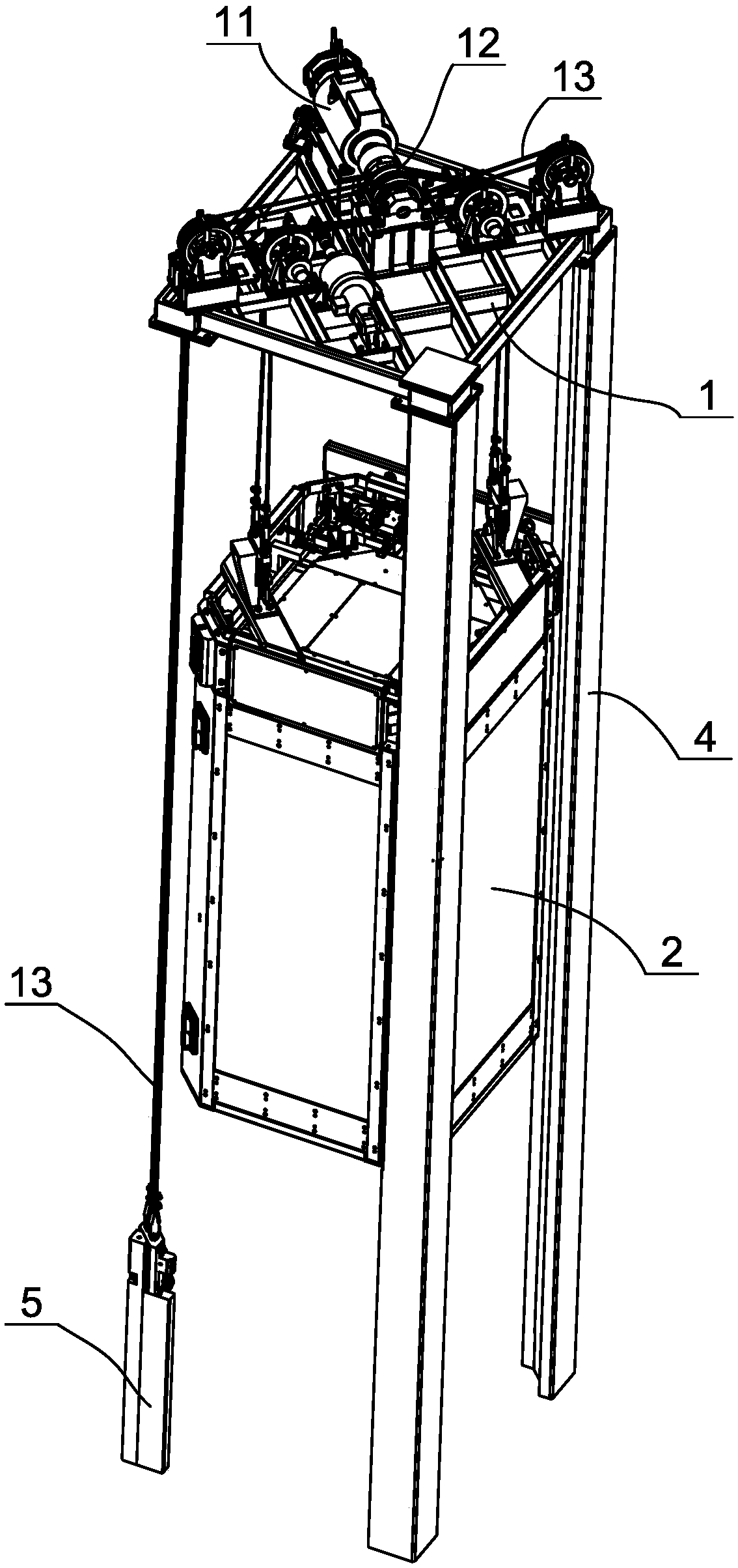
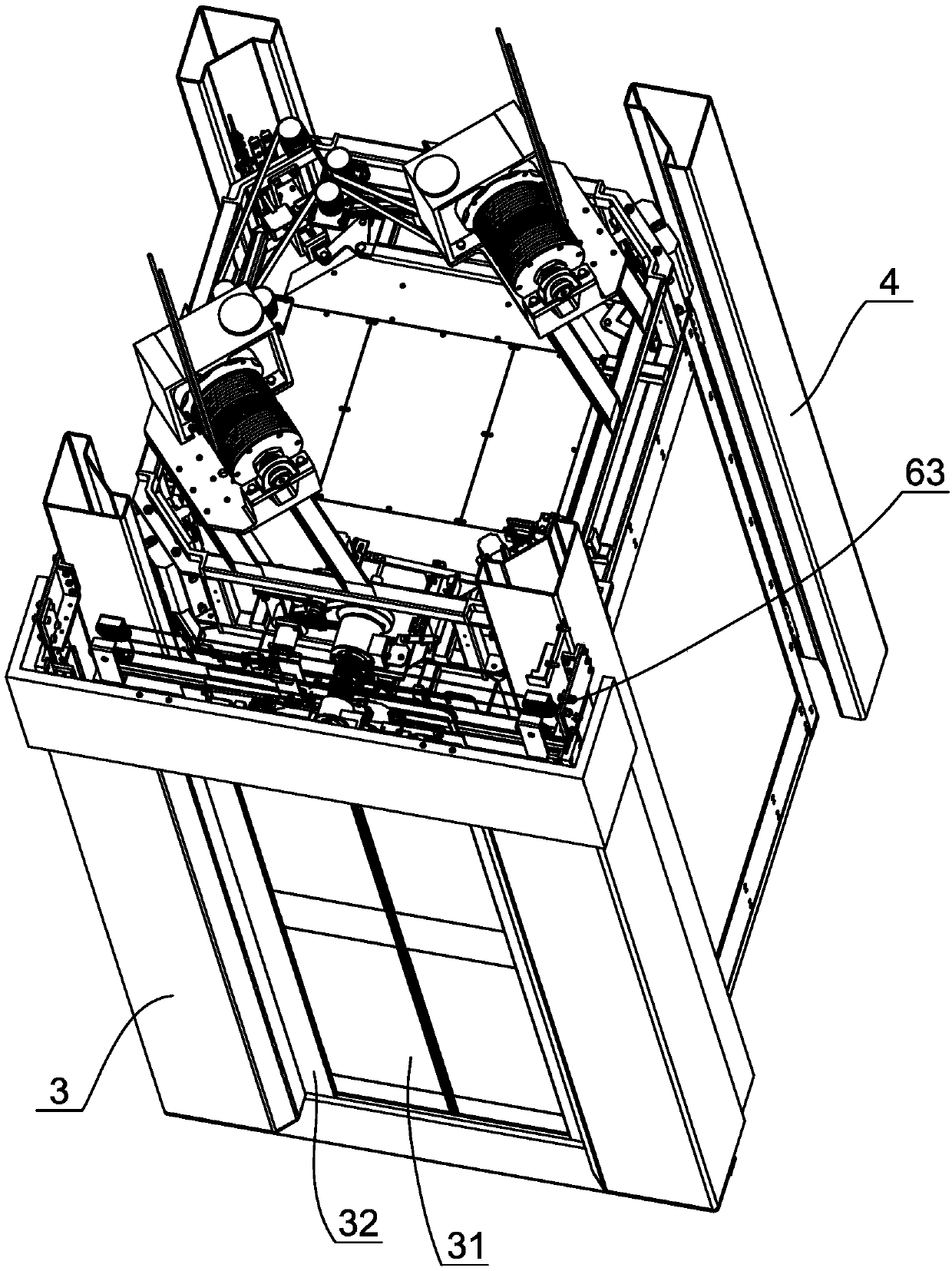
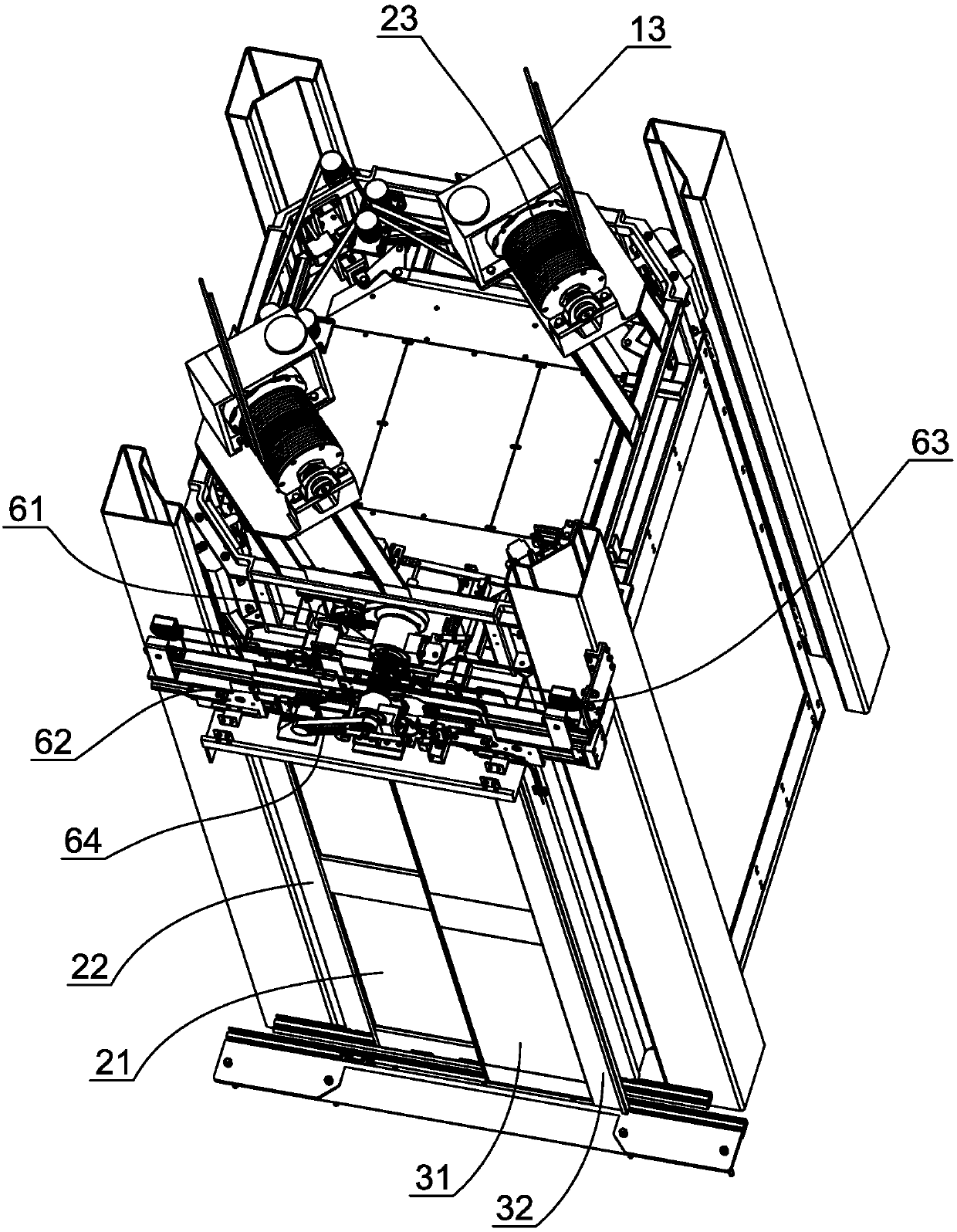
[0033] like figure 1 , figure 2 , image 3 As shown in the figure, an elevator floor door and car door structure with a small footprint includes a traction machine 11 arranged on the installation platform 1 at the top of the elevator shaft, a car 2 with a car door, and a hallway on each floor. The door frame 3 and the landing door movably arranged on the door frame are provided with hoistway columns 4 extending vertically downward at the four corners of the installation platform ( figure 1 2 are not shown), the hoistway column is made of extruded hollow structural profiles, thereby forming a vertical sliding cavity in the hoistway column. Guide rails extending in the axial direction are set on the outside of the hoistway columns, and guide shoes are installed at the four corners of the car between the four hoistway columns, and the guide sh...


PUM


Abstract

The invention discloses an elevator landing door and car door structure which is small in occupied space. The structure comprises a shaft stand column, an installation platform located at the upper end of the shaft stand column, an elevator car, a counterweight and a landing door connected to a door frame. The counterweight is movably positioned in the sliding cavity; a landing door driving mechanism is arranged on the door frame; a car door driving mechanism and a linkage mechanism capable of enabling the car door driving mechanism and the landing door driving mechanism to form linkage are arranged on the car; the car door comprises a left car door and a right car door. Each of the left car door and the right car door comprises a main car door and an auxiliary car door; the landing door comprises a left landing door and a right landing door, the left landing door and the right landing door each comprises a main landing door and an auxiliary landing door, and when the car door drivingmechanism drives the main car door and the auxiliary car door of the left car door and the right car door to relatively move to the door opening position, the linkage mechanism enables the landing door driving mechanism to synchronously drive the main landing door and the auxiliary landing door of the left landing door and the right landing door to relatively move to the door opening position. Thestructure can be conveniently and freely arranged in multiple directions, the occupied space of a hoistway can be remarkably reduced, and meanwhile the overall impression of an elevator can be improved.

Description

technical field [0001] The invention relates to the technical field of elevator manufacturing, in particular to an elevator landing door and car door structure that occupies a small space. Background technique [0002] In high-rise buildings, the elevator is a necessary accessory equipment, which can bring great convenience to the occupants. At present, with the development of the economy, a large number of middle and high-income groups have emerged, and the demand for villas is also increasing. Correspondingly, home elevators suitable for villa buildings have also become popular. The elevator mainly includes a shaft, a car that can be lifted and lowered in the shaft, and a drive mechanism for driving the car to go up and down. The traction machine is connected to the traction wheel, and a traction rope is wound around the traction wheel. One end of the traction rope is connected to the car, and the other end is connected to a counterweight that can be lifted and lowered in...

Claims


Application Information

Patent Timeline
Patent Type & Authority Applications(China)
IPC IPC(8): B66B13/30B66B11/04B66B13/16
CPCB66B11/043B66B13/165B66B13/30
Inventor 陈庆邓健李军
Owner SHAANXI SIUSAI ELECTROMECHANICAL TECH CO LTD
Why Eureka
Try Eureka